


4
SECTION 1 – ASSEMBLY INSTRUCTIONS
INTRODUCTION
The #6-3131 Clamshell Grass Catcher kit fits
Snapper Lawn Tractors, 1999 Series “D” and later
models, equipped with 33” decks and Cast Iron
Front Axles. Use the following instructions to
assemble the Grass Catcher components and
prepare your machine for collecting grass clippings
and leaves. Follow and complete each step
carefully.
WARNING
DO NOT attempt any adjustments, maintenance or
service with the engine running. STOP engine.
STOP blade. Engage parking brake. Remove key.
Remove spark plug wire from spark plug and
secure wire away from spark plug. Engine and
components are HOT. Avoid serious burns, allow
all parts to cool before working on machine.
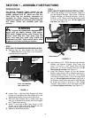
STEP 1
RIGHT AND LEFT BUMPER BRACKET INSTALLATION
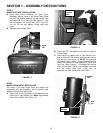
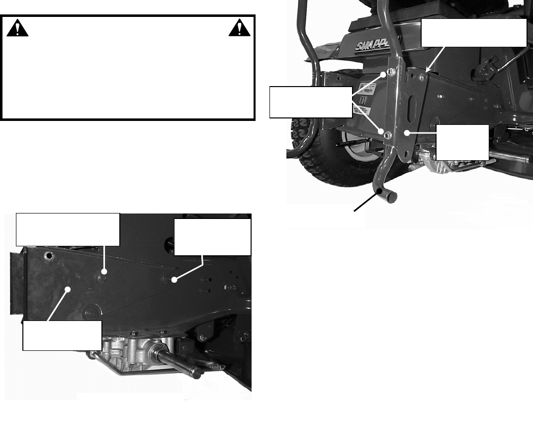
A. Remove right rear Seat Support bolt. See Figure
1.1. Note: Removal of rear tires is not required to
complete Bracket installation.
FIGURE 1.1
B. Loosen Only – right front Seat Support bolt. Back
bolt out only enough to allow the slotted hole in the
right Bumper Bracket to slip under head of bolt.
C. With front Seat Support bolt in slotted hole, align
rear hole in Bracket and reinstall rear Seat Support
bolt. Tighten bolts securely.
D. Series “F” and Later models Only: Place (1) 5/16-
18 hex nut on each right Seat Support bolt and
tighten securely against inside of frame.
E. Repeat for left Bumper Bracket.
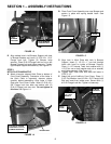
STEP 2
RIGHT AND LEFT BUMPER SUPPORT INSTALLATION
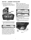
A. Install Rear Bumper and right Bumper Support to
the right Bumper Bracket. Align holes in Bumper
Support, Bumper and Bumper Bracket. Insert (2)
5/16-18 x 1-3/4” Flange Lock bolts and secure with
(2) 5/16-18 Flange Lock nuts. Do Not tighten at
this time. See Figure 1.2.
FIGURE 1.2
B. Insert Spacer (P/N 7-3272) between right Bumper
Bracket and Bumper Support. Align holes and
insert (1) 5/16-18 x 1-3/4” Flange Lock bolt and
secure with (1) 5/16-18 Flange Lock hex nut. Do
Not tighten at this time. See Figure 1.2.
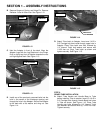
C. Install left Bumper Support to the left Bumper
Bracket. Align bottom hole in Bumper with hole in
Bumper Bracket. Insert (1) 5/16-18 x 1-3/4” Flange
Lock bolt and secure with (1) 5/16-18 Flange Lock
hex nut. Do not tighten at this time. Align hole in
left Bumper Support with top hole on Rear Bumper
as shown and insert (1) 5/16-18 x 1-3/4” Flange
Lock bolt. Secure with (1) 5/16-18 Flange Lock hex
nut. Do not tighten at this time. See Figure 1.3.
REAR SEAT SUPPORT
BOLT (REMOVE)
RIGHT BUMPER
BRACKET
FRONT SEAT
SUPPORT
BOLT
NOTE: TIRE REMOVED
FOR CLARITY ONLY
BUMPER BOLTS
5/16-18X1-3/4”
REAR BUMPER
SPACER
(HIDDEN IN THIS VIEW)
RIGHT
BUMPER
SUPPOR