


8
Adjustments
D
E
A
B
C
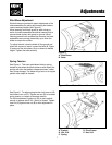
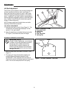
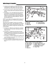
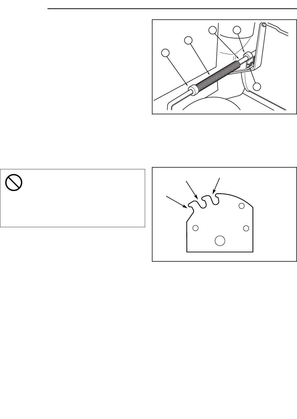
Figure 6. Adjusting Lift Rod
A. Front Set Collar
B. Rod Guide
C. Spring
D. Rear Set Collar
E. Spring Clip
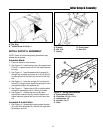
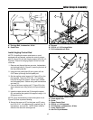
Figure 7. Lift Lever Quadrant - Side View
Notch 1
Notch 2
Notch 3
Lift Rod Adjustment
The lift lever can be placed in one of three notches and
is held in position by the lever latch. (see Figure 7).
When the lever latch is placed in notch 1 the lift lever
should be applying downward pressure on the attach-
ment. In position 2, the “float” position, the attachment
should experience negligible upward or downward pres-
sure. Position 3 should raise the attachment approxi-
mately 6“ above the ground.
NOTE: Always adjust the lift height before and after
adjusting the downward pressure.
LIFT HEIGHT ADJUSTMENT
1. Place the lever latch in notch 3 (see Figure 7). The
snowthrower should be approximately 6” off the
ground. If not, go to step 2.
2. Lower the attachment and adjust the front set collar
(A, Figure 7) to achieve the correct lift height.
DOWNWARD PRESSURE ADJUSTMENT
1. Move the lever latch from notch 2 to notch 1 (See
Figure 7).
2. The spring (C, Figure 6) should be slightly com-
pressed applying downward pressure to the
snowthrower. If not, adjust the rear set collar (D,
Figure 6) to achieve the desired amount of downward
force. Do not over-compress the lift rod spring.
IMPORTANT NOTE
DO NOT OVER-COMPRESS THE SPRINGS.
In addition to providing downward pressure,
the springs are an elastic medium that
absorbs shocks caused by bumps and
cracks in ground surfaces. Over-compress-
ing the springs defeats this and may cause
damage to the unit.