


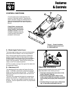
11
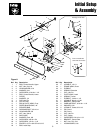
Initial Setup & Assembly
INITIAL SETUP & ASSEMBLY
NOTE: Some of the following setup procedures may
already be completed.
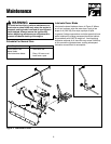
Assemble Blade
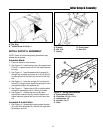
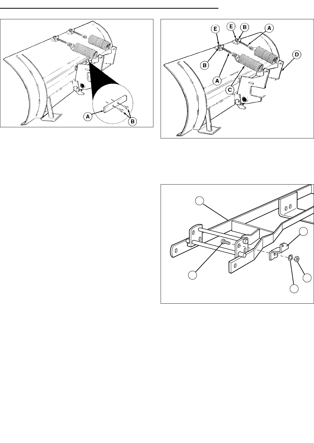
1. Place the blade on a flat surface.
2. See Figure 10. Install one bar stop (A) using the two
5/16-18 x 1 taptite screws (B). Do not install second
bar stop.
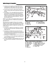
3. See Figure 11. Insert threaded end of eyebolt (A)
through lug on blade, and screw on 5/16 nut (B) just
far enough so that it is flush with the end of the eye-
bolt.
4. See Figure 11. Hook the springs (C) into the pivot
frame (D). Using a pliers, stretch the springs to hook
the opposite ends to the eyebolts (A).
5. See Figure 11. Tighten the nut (B) on each eyebolt
enough to expose about 3/4" (19 mm) of thread.
6. See Figure 11. Holding the first nut (B) with a
wrench,add a second nut (E) to each eyebolt, and
tighten securely against the first nut to act as a jam
nut.
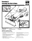
Assemble & Install Hitch
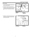
1. See Figure 12. Assemble the spring-assist bracket
(A) to the hitch assembly (E). Secure with capscrew,
lockwasher, and nut.
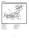
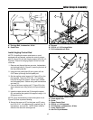
Figure 10. Bar Stop
A. Bar Stop
B. Taptite Screw, 5/16-18 x 1
Figure 11. Tension Springs
A. Eyebolt D. Pivot Frame
B. Nut, 5/16 E. Nut, 5/16
C. Spring
Figure 12. Spring Assist Bracket
A. Spring Assist Bracket
B. Capscrew, 1/2-13 x 1-1/4
C. Lockwasher, 1/2
D. Hex Nut, 1/2-13
E. Hitch
B
D
C
A
E