


15
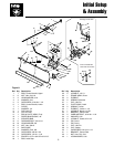
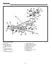
Initial Setup & Assembly
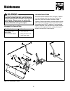
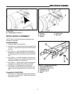
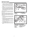
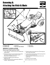
Figure 21. Underside of Left Footrest.
A. Carriage Bolt, Lockwasher, & Nut
B. Pedal Plate
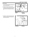
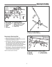
Figure 22. Control Rod Support
A. Support
B. 5/16-18 x 1-1/4 Carriage Bolts
C. 5/16 Lockwashers & Nuts
A
B
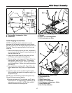
Install Angling Control Rod
NOTE: If installing the dozer attachment on a unit
equipped with a snowcab, replace the control rod sup-
port (A, Figure 22) with the hanging support (Ref. No. 41,
Figure 8). Mount the hanging support to the front cab
cross-bar.
1. Remove and discard the two rear nuts, lockwashers,
and carriage bolts (A, Figure 21) securing the back of
the foot pedal plate (B).
2. Using the foot pedal plate (B) as a guide, drill two
5/16” holes up through the foot pedal pad.
3. Set the angling control support (A, Figure 22) on the
foot rest pad. Insert two 5/16-18 x 1-1/4 carriage
bolts (B) through the support, footrest pad, footrest,
and foot pedal plate. Secure using new lockwashers
and nuts (C).
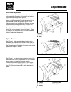
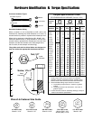
4. Connect the lower angling rod (F, Figure 23) to the
dozer release lever using a hair pin clip and washer
(G).
5. Insert the upper control rod (C) through the eyelet
(B), and secure the eyelet to the support using a 1/4-
20 nylock nut (A).
NOTE: It may be necessary to leave the eyelet nut (A,
Figure 23) loose to prevent binding.
6 Secure the upper rod (C) to the lower rod (F) using
two 5/16-18 x 1-1/4 capscrews (D), washers (qty. 4),
lockwashers, and nuts (E). NOTE: Match offset to
offset so the rods form a straight line.
A
B
C
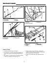
Figure 23. Assemble Control Rods
A. 1/4-20 Nylock Nut
B. Eyelet
C. Upper Control Rod
D. 5/16-18 x 1-1/4 Capscrew
E. 5/16 Washers, Lockwashers, & Nuts
F. Lower Control Rod
G. Hair Pin Clip & Washer
A
B
C
D
F
G
E