C
A
B
12
Initial Setup & Assembly
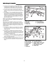
2. Increase front tire pressure to 20 psi (138 kPa) to
compensate for added weight of the hitch, plus bar
and blade. Be sure both tires have equal pressure.
3. From the front of tractor, slide the hitch under the
tractor so that the hitch bar is positioned at the front of
the unit.
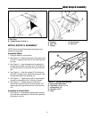
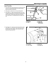
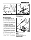
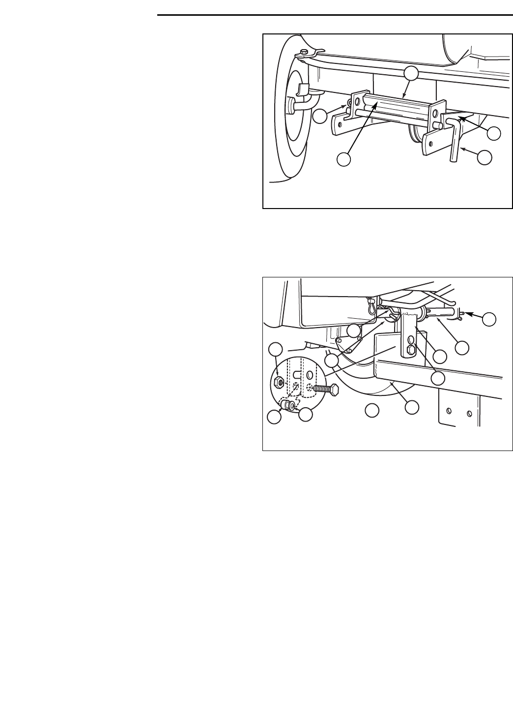
4. See Figure 13. Turn the wheels fully left and lift the
front hitch bar (A) up onto the tractor brackets (D).
Make sure it is fully seated into the tractor brackets.
Install the long hitch pin (B) through the bracket (bot-
tom rear holes) and up-stop brackets (E). Secure it
with the safety clip (C).
NOTE: If your tractor is not equipped with the Large Lift
Lever, install it at this time. Follow the instructions sup-
plied with the kit.
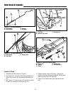
Note that the rear bracket (A, Figure 14) is mounted
using the lift lever rod (B). After installation, the lift lever
rod assy. can be removed by pivoting the lift lever fully
forward until it is parallel to the ground, and sliding it out
of the quadrant
5. See Figure 14. Slide the rear bracket (A), and wash-
ers (D), onto the lift lever shaft, and secure with the
hairpin clips (C).
6. See Figure 14. Position the rear plate of the hitch
assembly between the hanger tabs on the rear brack-
et, and secure at the top mounting hole using the cle-
vis pin (F), and hairpin clip (K).
7. See Figure 14. Install the capscrew (G), spacers (H &
I), and whizlock nut (J) in the lower mounting hole as
shown, and tighten securely.
8. The hitch assembly is now assembled to the unit, and
you may proceed to installation of the push bar and
blade.
J
I
H
D
C
A
F
E
G
B
Figure 14. Installing Hitch to Rear Bracket
A. Rear Bracket G. Capscrew, 3/8-16 x 2
B. Lift Lever Rod H. Spacer, 25/64 x 5/8 x 17/64
C. Hairpin Clip I. Spacer, 13/32 x 1 x 13/16
D. Washer J. Nut, Whizlock, 3/8-16
E. Hitch K. Hairpin Clip
F. Clevis Pin
Figure 13. Installing Hitch to Front of Tractor
A. Hitch Bar D. Tractor Brackets
B. Hitch Pin E. Up-Stop Brackets
C. Safety Clip
D
K
E


