


Mounting Hitch
1. Park tractor on a hard level surface.
2. Stop engine, lock parking brake, and remove key.
3. Place hitch on ground in front of tractor with pivot plate
facing away from tractor.
4. Rotate the hitch attaching links rearward toward the
tractor.
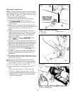
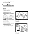
5. Install the back of hitch so that hitch pins (A, figure 5)
are cradled in tractor hitch bracket (B). The lift rod
front clevis must be positioned over the hitch lift arm
while raising hitch into position.
6. From inside hitch, install the left and right clevis pins
(C)through attaching links and tractor hitch bracket
(B). Secure with spring clips (D).
7. Align the holes in the lift rod front clevis and tractor lift
arm (may have to lift up on front hitch slightly). To
avoid interference, install the clevis pin (E) from inside
(flat head towards PTO belts). Secure the clevis pin
with spring clip on outside of lift arm clevis.
8. Check the “Transport Height Adjustment” procedure
on page 11 before snowthrower is installed.
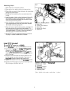
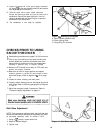
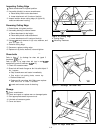
Install PTO Driveshafl
1.
Install l/4” x
1”
square key in keyway.
2. Install
driveshaft
(A, figure 6) with setscrew over key.
3. Secure the driveshaft with l/4-20
x
1
7/8”capscrew
(Grade 5) and i/4-20 locknut at location B.
NOTE: 1/4-20x l-7/8 capscrew supplied in
kit
hard-
ware bag has been ground to exact/y l-7/8 length for
use in this step.
4. Rotate the PTO driveshaft and check clearance with
the flat bearing boss just underneath. Peen end of
capscrew to prevent locknut from backing off.
5. Tighten the setscrew over key with
3/16”
allen
wrench.
6. Release the PTO support rod (C) from retaining hook
(D) and support driveshaft with rod.
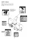
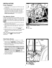
Figure 5. Mounting Hitch
A. Hitch Pins
B. Tractor Hitch Bracket
C. Clevis Pin
D. Spring Clip (Hitch)
E. Clevis Pin
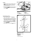
Figure 6. Installing PTO
Drvieshaft
(Snowthrower Side)
A. Driveshaft
B. Capscrew Location
C. PTO Support Rod
D. Retaining Hook
(Note: Hydraulic chute rotator model shown in photo.)
8