


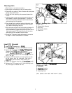
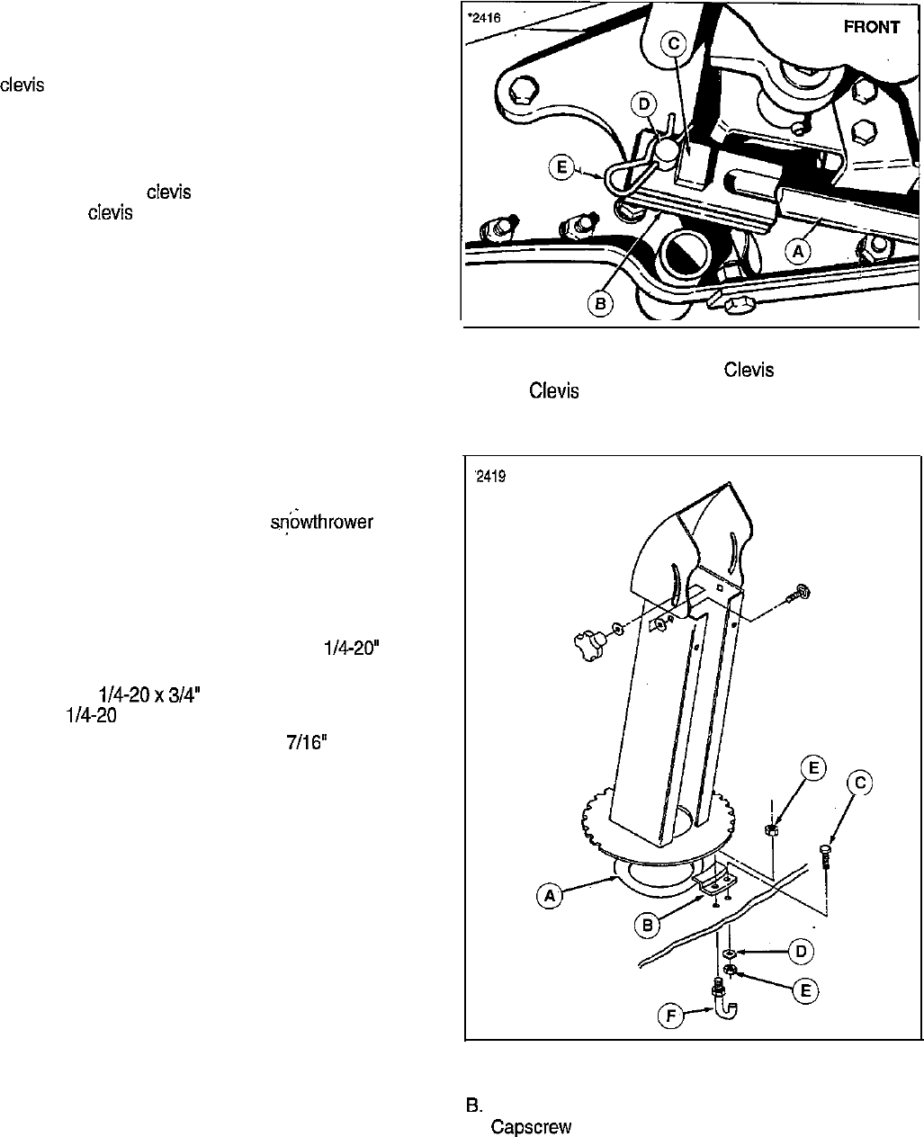
Lift Rod
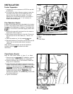
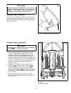
1. Lay lift rod (A, figure 3) next to the tractor so that rear
clevis (B) with square weldment (C) is towards the
rear. The weldment is positioned to prevent clevis pin
(D) from being installed from the right hand side
(interference would occur).
2. The lift rod must be inserted from the rear of the front
axle, aligning rear clews (B) with the tractor lift lever
(F). Install
clews
pin (D) from inside and secure and
spring clip (E).
Figure 3. Installing Lift Rod
A. Lift Rod D.
Clevis Pin
B. Rear Clews E. Spring Clip
C. Square Weldment F. Tractor Lift Lever
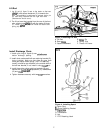
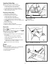
Install Discharge Chute
1. Install nylon ring (A, figure 4) over snowthrower
bottom discharge opening.
2. Install chute underneath left rear retaining bracket (B,
factory installed). Make sure that chute ring gear teeth
mesh with spiral rotator spring. The PTO retaining
hook(F) should be pre-installed in the outside hole of
the left rear bracket, if not, install it using
l/4-20” nut.
3. Install three other chute retaining brackets (B) and
secure with 1/4-20x
3/4”
capscrews (C), lo&washers
(D) and i/4-20 nuts (E).
4. Tighten hardware securely with two
7/16”
wrenches.
Figure 4. Installing Spout
A. Nylon Ring
8. Chute Retaining Bracket
C.
Capscrew
D. Lockwasher
E. Nut
F. PTO Retaining Hook
7