


6
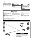
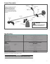
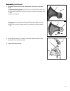
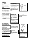
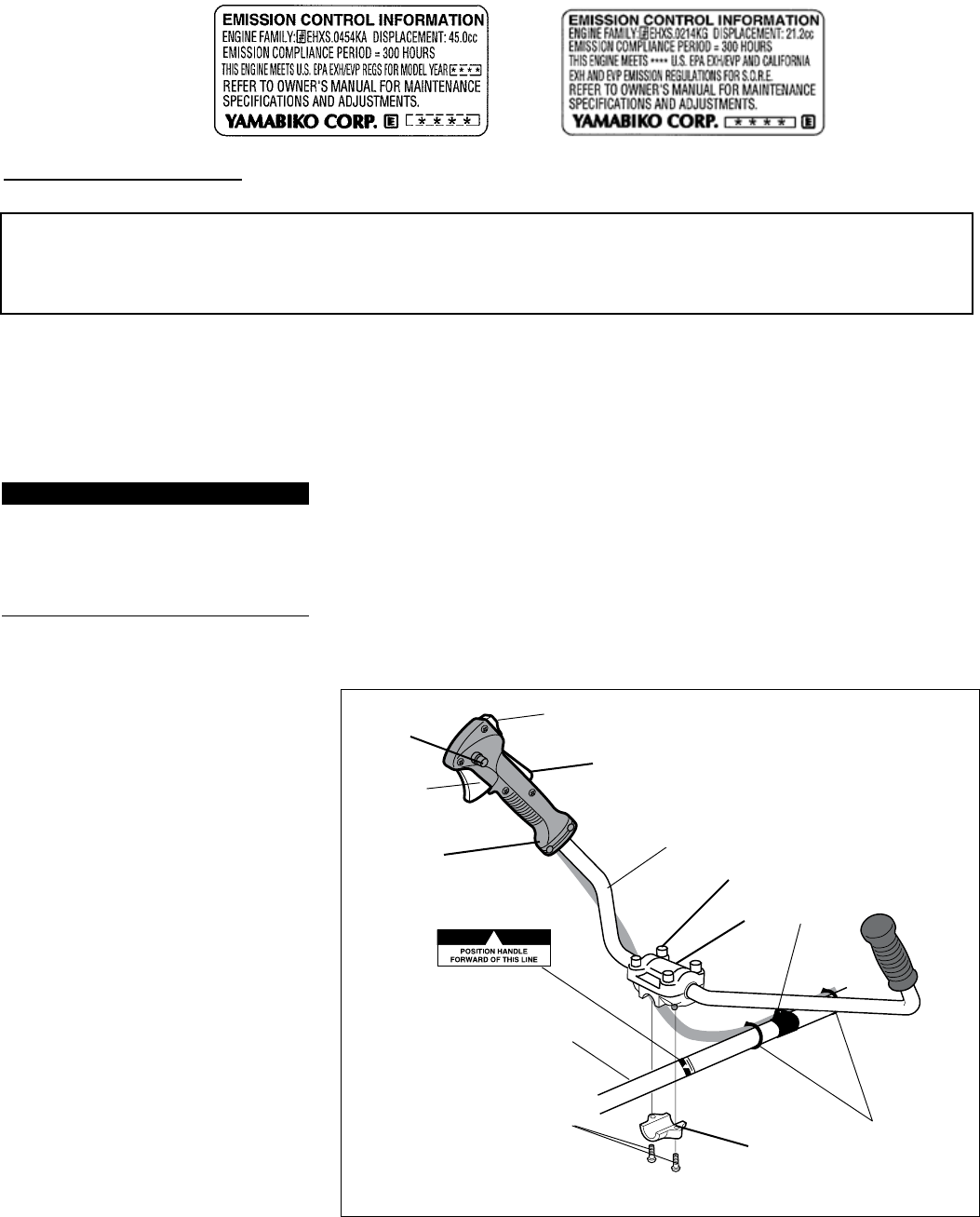
Handlebar and Throttle assemblyŶ
Handlebar C unit
Install the handlebar:
Use the 4 mm hex wrench to remove the 1.
lower cap retaining screws from the
handlebar bracket. Remove the cap
from the bracket.
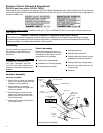
Position the handle on the outer tube for-2.
ward of Handle Positioning Label as
shown. Reassemble the lower cap to the
handlebar bracket in the reverse order
of disassembly.
Locate the handle in the best position for 3.
operator comfort.
Firmly tighten both lower cap retaining 4.
screws.
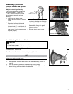
Secure the cable to the outer pipe with the 5.
2 bands as the illustration shows. The 2
bands are in the tool bag.
Outer tube
Lower cap
retaining
screws
Handlebar
Ignition switch
Throttle
trigger
Hanger
Mounting the brushcutter handlebar
Handle positioning
label
Bands
6
Assembly
This unit comes fully assembled with the
exception of the cutting attachment shield
and cutting attachment.
Prior to Assembly
Before assembling, make sure you have all
the components required for a complete
unit and inspect unit and components for
any damage.
Engine and shaft assembly
Ŷ
Cutting attachment shieldŶ
Cutting attachmentŶ
Kit containing cutting attachment Ŷ
shield, mounting bracket and hardware,
this owner’s/operator’s manual and tool
kit for routine maintenance. Tool kits
vary by model and may include a spark
plug/screwdriver combination wrench,
and a scraper.
IMPORTANT!
The terms “left”, “left-hand”, and “LH”;
“right”, “right-hand”, and “RH”; “front” and
“rear” refer to directions as viewed by the
operator during normal operation.
This unit comes fully assembled with the
exception of the cutting attachment shield
and cutting attachment.
Assembly
Prior to Assembly
Before assembling, make sure you
have all the components required for
a complete unit and inspect unit and
components for any damage.
Engine/Outer tube assembly
■
Handlebar and Throttle assembly ■
Cutting attachment shields ■
This unit comes fully assembled with
the exception of the handlebar, cut-
ting attachment shield and cutting
attachment.
Cutting Attachment
■
Shoulder Strap w/Hip Pad ■
Cutting attachment shield mounting ■
brackets and assembly hardware
Cutting attachment adapter plates
■
4 mm hex key wrench (Also use as ■
a locking tool)
T-wrench
■
IMPORTANT!
The terms “left”, “left-hand”, and
“LH”; “right”, “right-hand”, and “RH”;
“front” and “rear” refer to directions as
viewed by the operator during normal
operation.
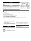
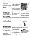
An Emission Control Label is located on the unit. (This is an EXAMPLE ONLY; information on label varies by en-
gine FAMILY).
PRODUCT EMISSION DURABILITY (EMISSION COMPLIANCE PERIOD)
The 300 hour emission compliance period is the time span selected by the manufacturer certifying the engine
emissions output meets applicable emissions regulations, provided that approved maintenance procedures are
followed as listed in the Maintenance Section of this manual.
Emission Control (Exhaust & Evaporative)
EPA 2010 and Later and/or C.A.R.B. TIER III
The emission control system for the engine is EM/TWC (Engine Modication and 3-way Catalyst) and for the fuel tank
the Control System is EVAP (Evaporative Emissions) or N (for nylon tank). Evaporative emission may be applicable to
California models only.
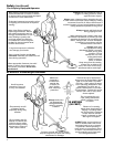
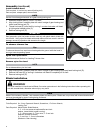
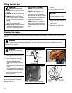
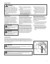
Install the handlebar:
Remove four (4) upper cap retaining 1.
screws, and remove upper cap from
handlebar mounting bracket.
Place handlebar on mounting 2.
bracket, and secure with upper cap
and four (4) screws.
Adjust handlebar position for best 3.
operator comfort and control, then
tighten upper and lower cap retain-
ing screws securely.
Secure cable to outer tube with two 4.
(2) bands provided.
Throttle lock
button
Throttle interlock
Throttle
Assembly
Upper cap
retaining screws
Upper
cap
Lower cap
Handle bar
Handlebar Assembly