


10
WARNING!
Alternative fuels, such as E15 (15% ethanol), E-85 (85% ethanol) or any fuels not meeting Shindaiwa
requirements are NOT approved for use in Shindaiwa gasoline engines. Use of alternative fuels may cause
performance problems, loss of power, overheating, fuel vapor lock, and unintended machine operation, including,
but not limited to, improper clutch engagement. Alternative fuels may also cause premature deterioration of fuel
lines, gaskets, carburetors and other engine components.
Fuel Requirements
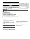
Gasoline - Use 89 Octane [R+M/2] (mid grade or higher) gasoline known to be good quality. Gasoline may contain
up to 10% Ethanol (grain alcohol) or 15% MTBE (methyl tertiary-butyl ether). Gasoline containing methanol (wood
alcohol) is NOT approved.
Hybrid 4
TM
Mixture Oil - Engine oil meeting ISO-L-EGD (ISO/CD 13738) and J.A.S.O. M345/FD standards must be
used. Shindaiwa highly recommends using Shindaiwa Red Armor
TM
engine oil in all Shindaiwa Hybrid 4
TM
engines to
protect the engine from harmful carbon build up, maintain engine performance, and increase engine life. Shindaiwa
Red Armor
TM
engine oil exceeds ISO-L-EGD and J.A.S.O. M345/FD performance requirements. Engine problems
due to inadequate lubrication caused by failure to use an ISO-L-EGD (ISO/CD 13738) and J.A.S.O. M345/FD certied
oil will void the engine warranty.
Mixing Fuel
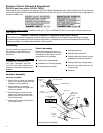
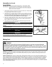
The unit should now be completely assembled and ready for use
with a blade.
IMPORTANT!
Discard blades that are bent, warped, cracked, broken or damaged in any way.
Use a sharp blade. A dull blade is more likely to snag and thrust.
D
A
K
G
L
H
D
K
H
G
L
A
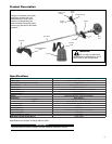
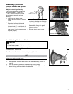
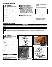
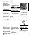
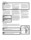
Install Blade
Tools Required: 4 mm hex key wrench (locking tool), 17 mm wrench, Pliers
Parts Required: Adapter plate w/25 mm diameter pilot, lower blade mounting
plate, 10 mm hex nut w/L.H. thread, 2 mm x 25 mm cotter pin,
blade w/25 mm arbor diameter.
1. Install adapter plate (D) on splined PTO shaft, pilot side down. Blade installa-
tion requires Upper Plate (D) with 25 mm pilot.
2. Install Blade (K) on adapter plate pilot. Blades must be installed so that rota-
tion arrow on blade matches rotation of unit: teeth toward direction of rotation
(See debris shield decal). Secure blade with Lower Plate (H), and 10 mm
L.H. nut (G). Turn nut counter-clockwise on PTO shaft to tighten.
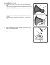
3. Align hole in adapter plate with notch in gear housing, and insert Locking Tool
(A) to prevent splined shaft from turning. Arrow on gear housing points to
notch. Tighten 10 mm nut securely.
4. Insert Cotter Pin (L) in hole in PTO shaft, and bend pin legs around shaft
counterclockwise to retain 10 mm nut.
IMPORTANT
Never reuse a cotter pin - install a new cotter pin each time a blade is installed or
replaced.
5. Remove locking tool.
Assembly (continued)