


7
23013
Assembly
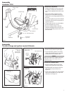
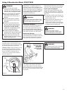
Throttle Linkage and Ignition Leads All Models
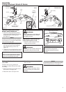
Remove the Cylinder Cover.
1. Remove the cap from the spark plug.
2. Loosen the black cylinder cover knob
(about a dozen full turns are required),
and then lift off the cylinder cover.
NOTE:
If the cover binds on the muffler outlet tube,
pull gently on the corner of the cover as
shown (see inset).
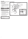
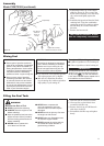
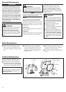
Connect the Throttle Cable.
1. Route the ribbed cable over the tube
clamp to the top left side of the engine.
2. Install the black wire between the two
cable adjuster nuts as shown. See
Figure 11.
3. Connect the S-shaped end of the throttle
cable to the throttle lever on top of the
carburetor. See Figure 12.
Install the black wire
between the two cable
adjuster nuts.
Connect the
throttle cable
Ignition
Ground
Lead
Cable Adjuster Nut
Figure 11
Figure 12
23014
Loosen the
cylinder cover
knob and
disconnect the
spark plug cap
Lift the corner of
the cover
Figure 10
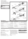
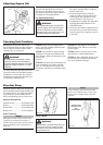
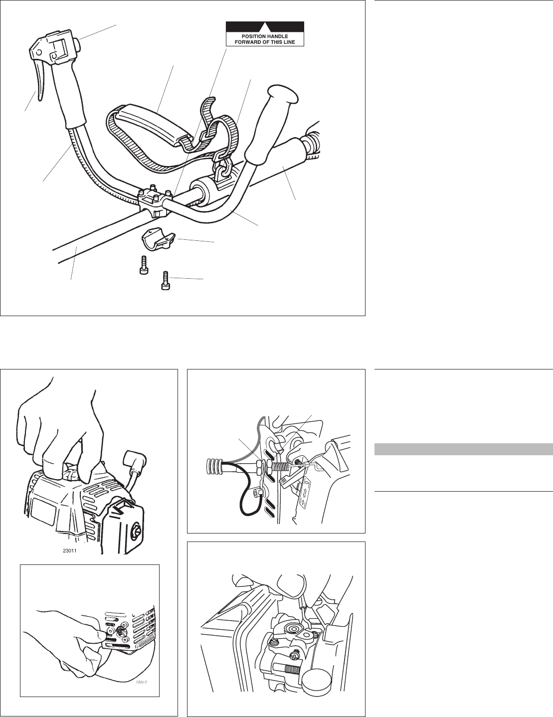
Handle Positioning Label
Assembly
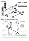
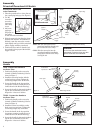
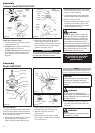
Handlebar C230
Assemble the Handlebar.
1. Position the handle over the outer tube.
See Figure 9. Make sure the throttle le-
ver is on the right-hand side of the outer
tube.
2. Attach the handle mounting bracket
using the two socket-head cap screws.
Tighten the screws finger-tight ONLY at
this time.
3. Locate the handle forward of the Handle
Positioning Label at the best position for
operator comfort.
4. Using the hex wrench, securely tighten
the two handlebar cap screws.
5. Route the ribbed throttle cable tube
along the handlebar and outer tube. See
Figure 9. Install the protector sleeve on
the outer tube.
Outer Tube
Mounting Bracket
Socket-Head
Cap Screw
Throttle
Cable
Handlebar
Protector Sleeve
Figure 9
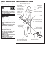
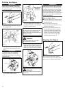
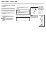
Ignition Switch
Throttle
Trigger
Hanger
Shoulder Strap