


10
Assembly
Trimmer Head C230/T230/T230X
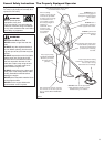
WARNING!
A standard grass trimmer unit with loop
handle should NEVER be operated with
blade-type attachments. For blade use,
the trimmer must be tted with a bicycle-
type handlebar or barrier bar that is lo-
cated in front of the operator to reduce the
risk of the operator coming in contact with
the cutting attachment. (Per ANSI B175.3).
When using a blade, the unit must be
equipped with a harness or strap.
23019
Remove the
retaining
plug
Install the
trimmer
head
Model
T230
Model
C230/T230X
Holder B
Holder A
Holder
A
Thread
on the
trimmer
head
Holder
B
Holder
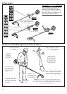
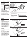
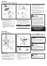
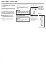
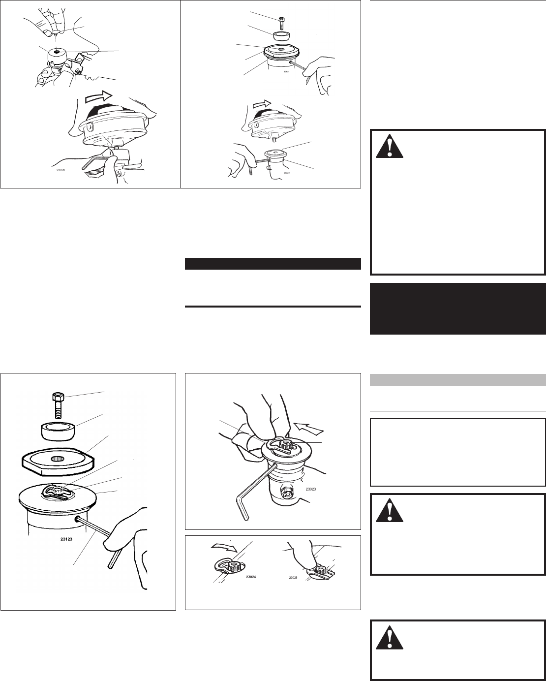
Install the Trimmer Head.
1. Turn the unit over so that the gearcase
output shaft faces UP.
2. (T230) Remove and discard the plastic
retaining plug. See Figure 16.
(T230X/C230) Remove the shaft bolt
and bolt guard using the combination
spark plug wrench/screwdriver. See
Figure 17.
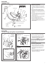
3. Rotate the holder until the hole in the
holder aligns with the notch on the
gearcase flange. Use the long end of the
hex wrench to lock the output shaft in
position. See Figure 16 or 17.
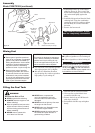
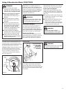
IMPORTANT!
The trimmer head has a left-hand thread.
Turn the trimmer head counter-clockwise
to install and clockwise to remove.
The 230 unit should now
be completely assembled
and ready for use as a
grass trimmer.
Figure 16
Figure 17
Output
Shaft
Output
Shaft
Bolt Guard
Shaft Bolt
4. While holding the hex wrench, thread
the trimmer head onto the output shaft,
turning counter-clockwise.
5. Using hand pressure only, tighten the
trimmer head firmly on the gearshaft.
6. Remove the hex wrench.
7. Adjust the trimmer line length to reach
no further than the line cutter on the
cutting attachment shield. Trim to the
correct length if necessary.
Shaft Bolt
Bolt Guard
Holder “B”
Gear Shaft
Holder “A”
Hex Wrench
Assembly
Blade C230/T230X
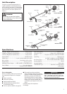
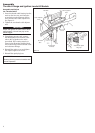
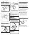
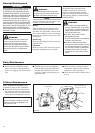
Mount the Blade.
Turn the brushcutter upside down so the
gearcase output shaft is facing UP, and re-
move the shaft bolt, bolt guard and holder
B from the gearcase shaft.
1. Align the hole in blade holder “A” with
the matching hole in the gearcase
flange, and then temporarily lock the
WARNING!
The blade must t at against the
holder ange. The blade mounting hole
must be centered over the raised boss
on blade holder A.
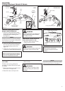
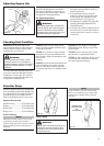
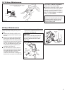
Slide the saw blade
in place
Center the safety
clip
CAUTION!
Install the blade so its printed surface
is visible to the operator when the
brushcutter is in the normal operating
position.
4. Lock the blade in place by centering
the safety clip on the output shaft. See
Figure 18.
WARNING!
Never operate the brushcutter without
the safety clip in place!
Figure 18
Figure 20
Safety
Clip
Output
Shaft
Figure 19
Slide the safety clip off-center
Safety Clip
output shaft by inserting a hex wrench
through both holes. See Figure 18.
2. Slide the safety clip off-center.
See Figure 18.
3. Fit the blade over the safety clip and
then center it over the flange on holder
“A”. See Figure 19.
NOTE:
When installing certain blades, it may be nec-
essary to temporarily remove the safety clip.