


7
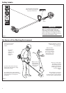
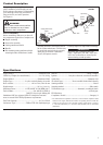
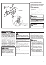
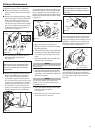
Assemble and Adjust
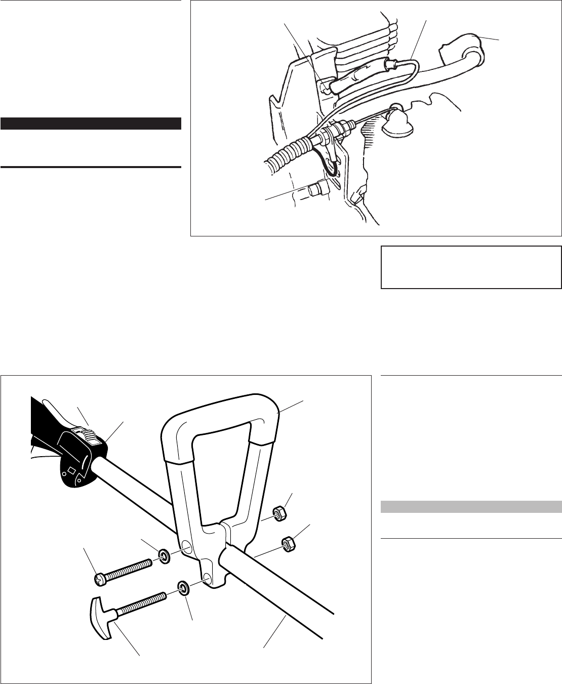
the Throttle Cable.
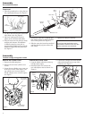
1. Insert the throttle cable housing into the
notch on the fan cover, and clamp the
black wire’s connector between the fan
cover and the cable outer adjuster nut.
See Figure 10.
2. Tighten the two throttle cable adjuster
nuts.
IMPORTANT!
Adjust and tighten the cable nuts to allow
approximately 1/4-inch free play at the
throttle trigger.
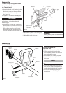
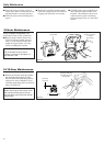
Spark
Plug Boot
Black Wire
Ignition Ground
Lead
Black Wire
3. Using finger pressure only, connect the
black switch wire from the cable tube to
the red ignition wire on the powerhead.
Wire routing must be as shown in the
illustration with the black wire located
over the spark plug wire. See Figure 10.
Throttle Linkage and Ignition Leads
Assembly
Red Wire
4. Reinstall the cylinder cover and tighten
the three cover screws.
5. Reinstall the spark plug boot.
CAUTION!
Routing of wiring must not interfere with
throttle operation.
26049
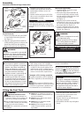
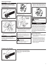
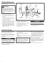
Handle LE231
Assembly
1. Remove both screws from the handle.
2. While spreading the handle at the
mounting hole, position the handle on
the outer tube as shown.
3. Reinstall the two mounting screws in
the handle, but do not tighten them at
this time.
NOTE:
The handle is recessed to receive the hex
nuts.
4. Locate the handle at the best position
for operator comfort (usually about 10
inches ahead of the throttle assembly).
5. Secure the handle by tightening the
mounting screw and the adjustment
knob screw.
Handle
Hex Nut
Washer
Hex Nut
Outer Tube
Adjustment
Knob
Mounting Screw
Washer
Connect the Handle to
the Outer Tube.
Figure 11
Throttle
Assembly
Ignition
Switch
Figure 10