


6
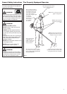
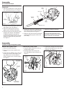
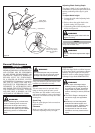
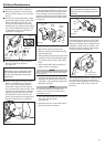
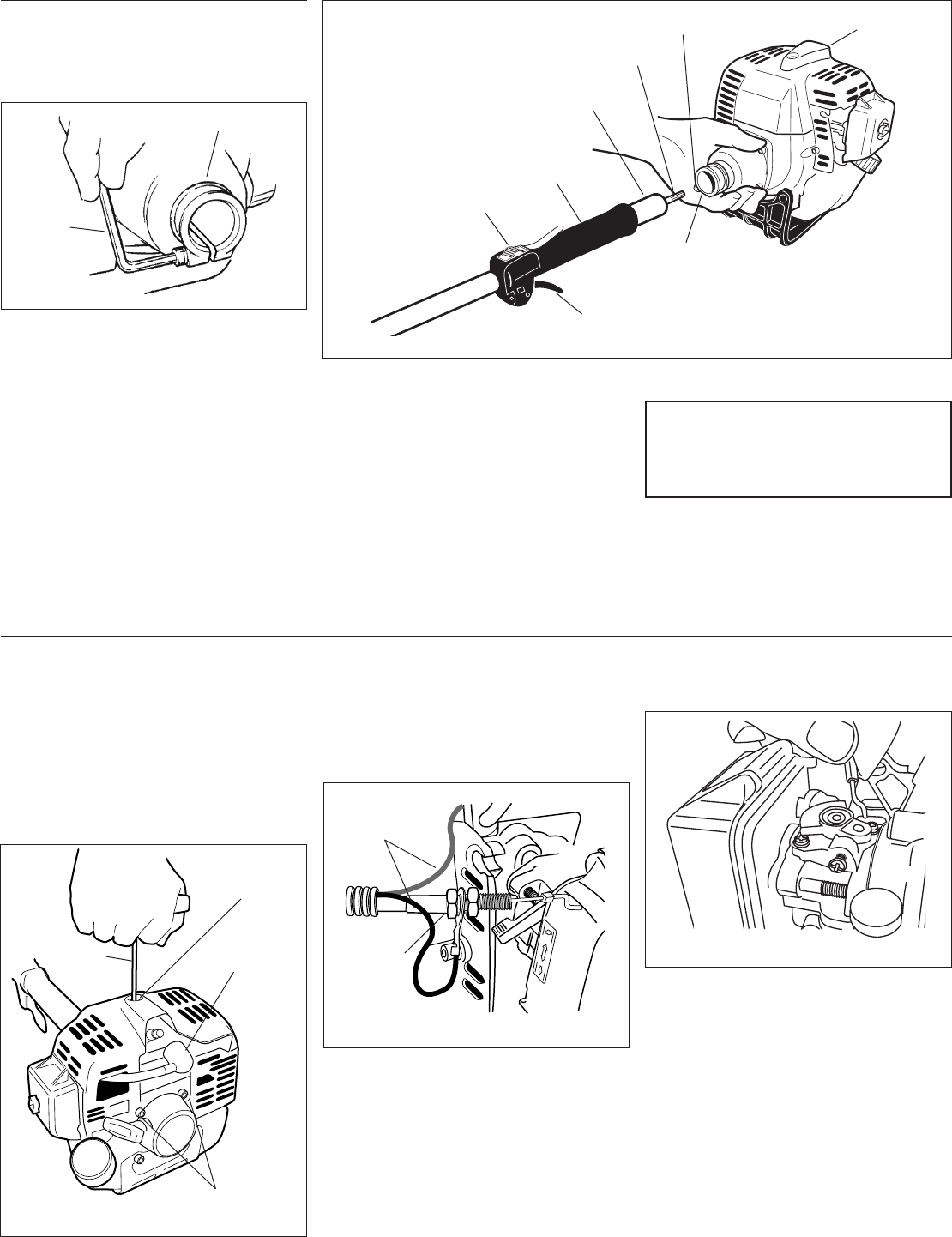
2. Use the 4 mm hex wrench to loosen the
tube clamp screw. See Figure5.
3. Add some moly-type EP grease to
splines at the end of the main shaft.
4. Slide the outer tube into the tube clamp
until the tube bottoms. If installation
is difficult, rotate the outer tube or
gearcase shaft slightly until you feel the
mainshaft engage with the powerhead.
See Figure 6.
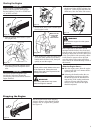
Grip
Spark Plug
Ignition
Switch
Main
Shaft
Tube
Clamp
Outer Tube
1. Place the powerhead on a clean, flat sur-
face, spark plug facing up. See Figure 5.
Tube Clamp
Hex
Wrench
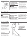
Connect the Outer Tube to the
Powerhead.
Clamp Screw
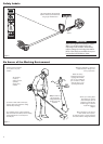
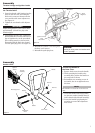
5. Position the outer tube so that the igni-
tion switch is facing up and the throttle
lever is facing down. See Figure 6.
6. Slide the outer tube into the powerhead
until the throttle grip just contacts the
tube clamp.
Figure 6
Figure 5
Throttle Lever
Driveshaft/Powerhead
Assembly
7. Tighten the clamp screw firmly.
CAUTION!
Do not force the shaft tube into the
powerhead! Excessive force can dam-
age the shaft tube and mainshaft.
23145
23106
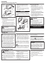
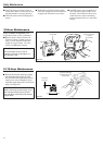
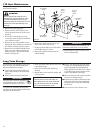
Remove the Cylinder Cover.
1. Remove the spark plug boot.
2. Remove the two lower cylinder cover
screws.
3. Loosen the top cylinder cover screw un-
til the cover is free of the engine. (The
top cylinder cover screw is captive).
Lift the cylinder cover off of the engine.
See Figure 7.
Connect the Throttle Cable.
Cable
Adjuster
Ignition
Leads
3. Connect the S-shaped end of the throttle
cable to the throttle lever on top of the
carburetor. See Figure 9.
1. Loop the ribbed cable tube to the top
left side of the engine.
2. Install the black wire between the
two cable adjuster nuts as shown. See
Figure 8.
Top Cylinder
Cover Screw
Lower Cylinder
Cover Screws
Hex Wrench
Figure 7
Figure 8
Spark Plug
Boot
23146
Throttle Linkage and Ignition Leads
Assembly
Figure 9