


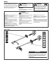
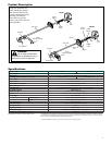
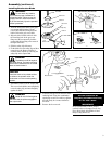
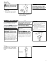
NOTE:
This unit is shipped with Holder A, the
blade retainer (safety clip), Holder B, shaft
bolt, and bolt guard installed. The shaft
bolt is a LEFT-HAND thread. Remove it
by turning CLOCKWISE!
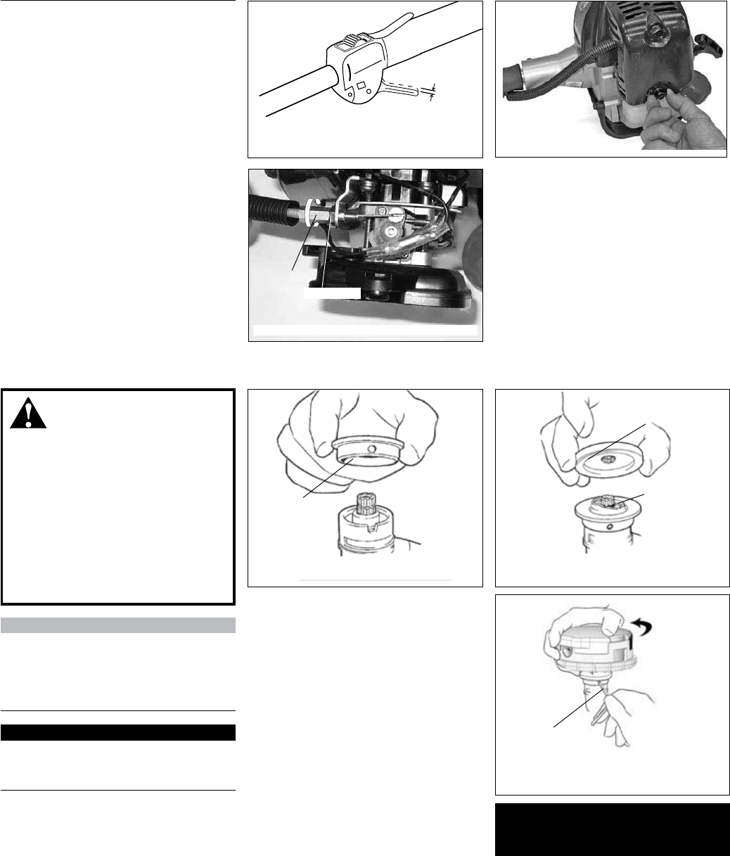
Install Holder
A
Install Holder
B
Safety Clip
Hex Wrench
Hand-tighten
trimmer head
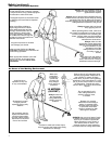
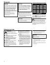
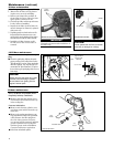
Throttle lever free play
4-6 mm
(3/16”-1/4”)
Throttle Free Play
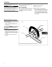
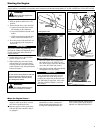
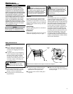
Position the gearcase with the output
shaft facing up
Securely tighten the trimmer head into the
gearcase shaft
Install and center the safety clip
Position the gearcase with the output 1.
shaft facing up and remove both holders.
Position Holder A as shown and slide it 2.
onto the gearcase shaft.
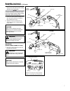
Install and center the safety clip on the 3.
gearcase shaft.
Install Holder B on the gearcase shaft. 4.
The machined boss on Holder A must
engage with the recess on Holder B.
Rotate the gearshaft and holders until 5.
the hole in Holder A aligns with the
matching hole in the gearcase flange,
and then lock the holder to the gearcase
by inserting the long end of the hex
wrench through both holes.
Using a counter-clockwise rotation 6.
and hand pressure alone, thread and
securely tighten the trimmer head into
the gearcase shaft.
Remove the hex wrench from the 7.
gearcase and holders.
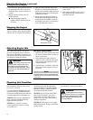
Adjust the trimmer line length to reach 8.
no further than the line cutter on the
cutting attachment shield. Trim to the
correct length if necessary.
IMPORTANT
To install a trimmer head onto a TX
unit, first remove the shaft bolt and
bolt guard.
The unit should now be
completely assembled and ready
for use with a trimmer head.
Install trimmer head
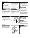
WARNING!
A standard grass trimmer
with a loop handle should NEVER
be operated with blade-type attach-
ments. For blade use, the trimmer
PXVWEH¿WWHGZLWKDELF\FOHW\SHKDQ-
dlebar or a barrier bar that is located
in front of the operator to reduce the
risk of the operator from coming in
contact with the cutting attachment
(per ANSI B175.3). When using a
blade, the unit must also be equipped
with a harness or strap.
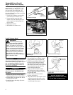
Remove air cleaner cover
Lock Nut
Cable
Adjuster
Adjust as required for 4-6 mm free play
8
Assembly (continued)
Adjust throttle lever free play
The throttle lever free play should be
approximately 4 - 6 mm (3/16” - 1/4”).
Make sure that the throttle lever oper-
ates smoothly without binding. If it
becomes necessary to adjust the lever
free play, follow the procedures and illus-
trations that follow.
Loosen the air cleaner cover knob(s) 1.
and remove the air cleaner cover.
Loosen the lock nut on the cable 2.
adjuster. Turn the cable adjuster in or
out as required to obtain proper free
play 4 - 6 mm.
Tighten the locknut.3.
Reinstall the air cleaner cover.4.