


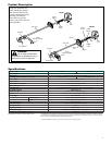
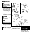
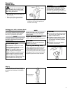
X uni
t
O
uter Tub
e
H
an
dl
e
B
a
rri
e
r B
a
r
4
S
ocket-head
capscre
w
s
H
an
dl
e
p
os
i
t
i
on
l
a
b
e
l
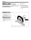
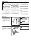
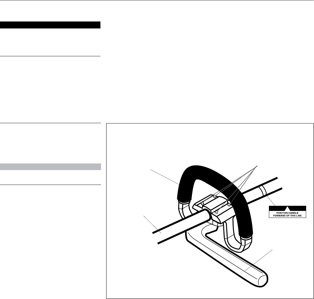
Th
e
h
an
dl
e is attac
h
e
d
at t
h
e factory an
d
p
ositione
d
vertica
ll
y
.
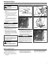
L
oosen soc
k
et
h
ea
d
e
d
capscrew
(
s
)
at
1.
the
base
o
f
ha
n
dle
a
n
d
r
otate
the
ha
n
-
dle 90 degrees
.
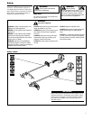
Handle and barrier bar X uni
t
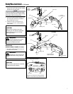
N
O
TE
:
K
eep handle forward of handle posi
-
t
ioning label!
P
os
i
t
i
o
n
t
h
e
h
a
n
d
l
e
f
o
rw
a
r
d
o
f
t
h
e
2.
Han
dl
e Positionin
g
La
b
e
l
at t
h
e
b
es
t
position for operator comfort
(
usua
lly
about 254 mm (10 in.) ahead of throttle
h
ousin
g)
.
Ti
gh
ten t
h
e soc
k
et
h
ea
d
e
d
ca
p
scre
w
3.
s
ecurel
y
.
R
otate and
p
osition handle in best location
f
or o
p
erator com
f
ort
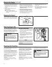
6
A
ssem
bly
T
his unit comes full
y
assembled with the
e
xception of the cutting attachment shield
a
n
d
cuttin
g
attac
h
ment
.
Prior to Assembl
y
B
efore assem
bl
ing, ma
k
e sure you
h
ave a
ll
t
h
e com
p
onents re
q
uire
d
for a com
pl
ete
u
nit and inspect unit and components for
a
ny
d
amage.
Engine an
d
s
h
aft assem
bly
Ŷ
Cuttin
g
attachment shiel
d
Ŷ
Cutting attachmen
t
Ŷ
K
it containing cutting attachment
Ŷ
s
h
ie
ld
, mountin
g
b
rac
k
et an
d
h
ar
d
ware,
this owner’s/o
p
erator’s manual and tool
kit for routine maintenance. Tool kits
vary
b
y mo
d
e
l
an
d
may inc
l
u
d
e a spar
k
p
lu
g
/screwdriver combination wrench,
a
nd a scraper.
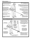
IMPORTANT!
Th
e terms “
l
eft”
,
“
l
eft-
h
an
d
”
,
an
d
“LH”;
“right”, “right-hand”, and “RH”; “front” and
“rear” refer to
d
irections as viewe
d
b
y t
h
e
o
p
erator
d
urin
g
norma
l
o
p
eration
.
T
his unit comes full
y
assembled with the
e
xce
p
tion of t
h
e cuttin
g
attac
h
ment s
h
ie
ld
and cuttin
g
attachment.