ASSEMBLY
2160 07/11 Assembly Section 3-8
© 2011 Alamo Group Inc.
ASSEMBLY
HOSES TO VALVE CONNECTIONS FOR ELECTRONIC CONTROL
(OPTIONAL)
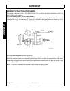
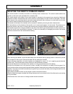
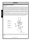
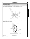
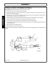
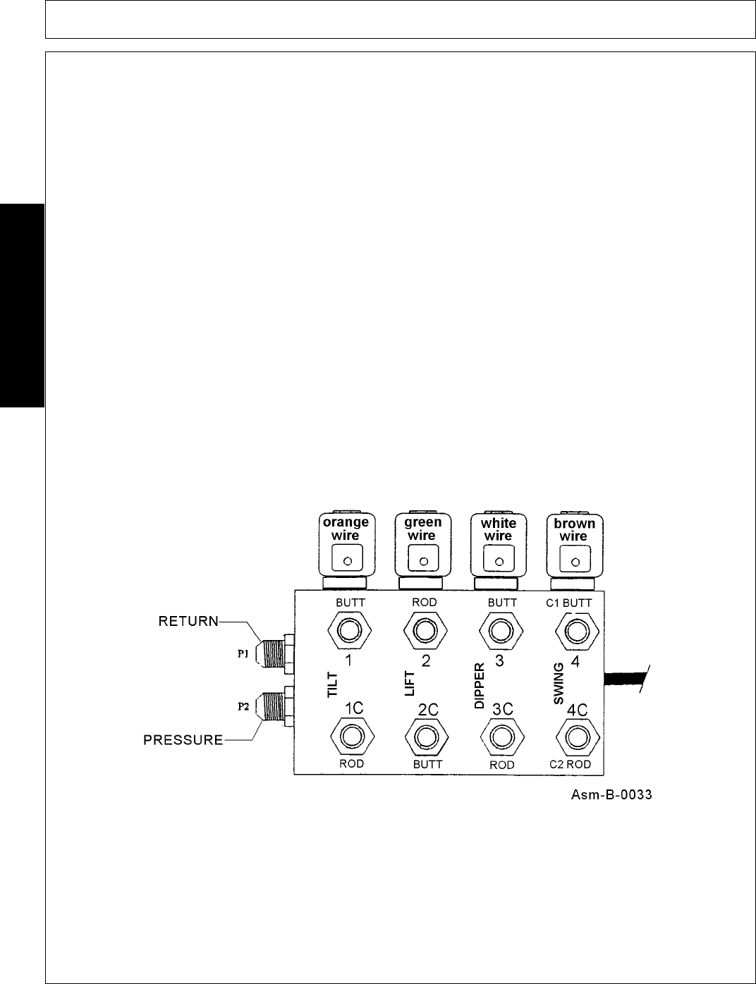
Refer to Asm-B-0032 & Asm-B-0030 and parts section page 6-24 for proper hose routing. Attach the electric
valve to the plate using the two 3/8 x 5 bolts, four 3/8 flatwashers, and two 3/8 lockwashers.
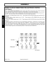
Connect the valve to open auxiliary hydraulic ports of the tractor. By connecting supply hoses to the valve "P1"
and "P2". Both valve hoses will be p/n 02961036. Use recommended torque values.
a. Connect Lift cylinder hoses to port 2 & 2C. These hoses are P/N 00765738 (Rod end) and P/N 001772
(Butt end).
b. Connect Dipper cylinder hoses to port 3 & 3C. These hoses are P/N 0283900 (Butt end) and P/N
00765737 (Rod end).
c. Connect Tilt cylinder hoses to port 1 & 1C. These hoses are P/N 02215700 (Butt end) and P/N 0221800
(Rod end).
d. Attach 90° elbows to the fittings on port 4 of the electronic valve block. Connect the "C1" and "C2" ports
of the breakaway valve to port 4 using hoses P/N 02965475. Connect the "B" port of the breakaway
valve to the rod end of the swing cylinder and connect the "A" port of the breakaway valve to the butt end
of the swing cylinder. The "A" port of the breakaway valve must be connected to the butt end of the swing
cylinder for proper operation of the breakaway feature! These hoses are P/N 02961321.


