


OPERATION
The operationofanyTiller canresultinforeign objectsthrownintotheeyes, whichcanresultinsevere
eye damage. Always wear safety glasses or eye shields before starting your Tiller and while tilling. We
recommend Wide Vision Safety Maskfor over the spectacles or standard safety glasses, available at
Sears Retail or Catalog Stores°
HOW TO USE YOUR TILLER
Know how to operate all controlsbeforeadding fuel and
oil or attempting to start Engine. (To stop Engine place
ThrottleControl in STOP position,)
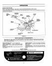
TINE OPERATION - WiTH WHEEL DRIVE
• Always release Drive Control Bar before movingShift
Lever intoanother position,
- Tine movement is achieved by movingShirt Lever to
"T" positionand engaging Drive ControlBar.,
FORWARD - WHEELS ONLY ! TINES STOPPED
• Release Drive Control Bar and move Shift Lever Indi-
cator to "F" position, Engage Drive Control Bar and
Tiller will move forward
REVERSE - WHEELS ONLY / TINES STOPPED
. DO NOT STAND DIRECTLY BEHIND TILLER
• Release the Drive Control Bar
• Move Throttle Control to "SLOW" position..
• Move Shift Lever Indicator to "R" position,
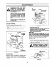
. Hold Drive Control Bar against the Handle (Fig. 11) to
start Tiller movement.,
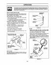
DRIVE CONTROL BAR
Z
BAR DISENGAGED _ \
POSITION _ \
FIGURE 11
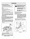
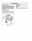
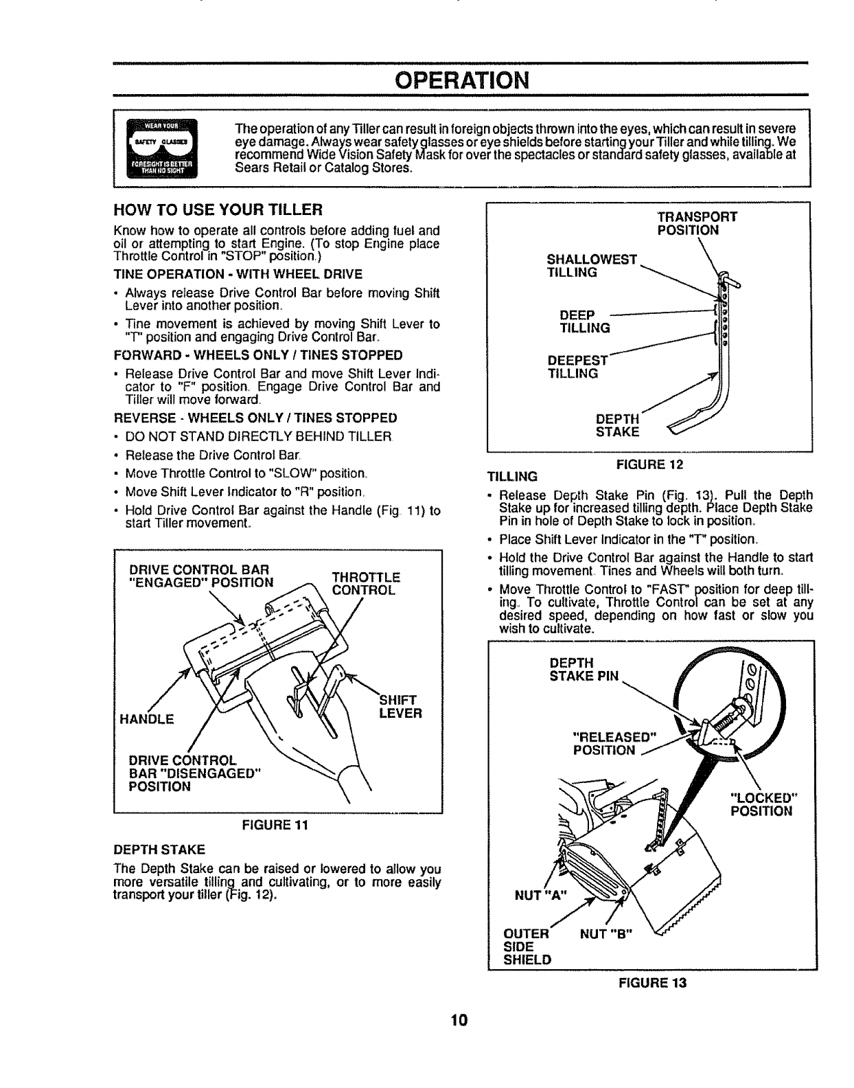
DEPTH STAKE
The Depth Stake can be raised or lowered to allow you
more versatile tilling and cultivating, or to more easily
transportyourtiller (Fig. 12)°
SHALLOWEST
TILLING
TRANSPORT
POSITION
DEEP
TILLING
TILLING
DEPTH
STAKE
FIGURE 12
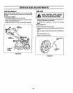
TILLING
. Release Depth Stake Pin (Fig. 13). Pull the Depth
Stake up for increased tilling depth. Place Depth Stake
Pin in hole of Depth Stake to lockin position.
• Place Shift Lever Indicator in the "T" position..
• Hold the Drive Control Bar against the Handle to start
tilling movement. Tines and Wheels will both turn.,
. Move Throttle Control to "FAST" position for deep till-
ing. To cultivate, Throttle Control can be set at any
desired speed, depending on how fast or slow you
wish to cultivate.
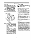
DEPTH
STAKE PIN
"RELEASED"
POSITION
"LOCKED"
POSITION
NUT "A"
OUTER
SIDE
SHIELD
NUT "B"
FIGURE 13
10