


28
M
K
L
P
Q
Q
R
S
P
R
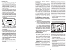
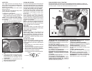
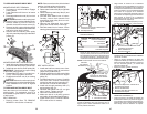
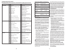
TO REPLACE MOWER DRIVE BELT
MOWER DRIVE BELT REMOVAL
1. Park tractor on a level surface. En gage
parking brake.
2. Lower attachment lift lever to its lowest
position.
3. Disengage belt tension rod (K) from lock
bracket (L).
CAUTION: Belt tension rod is spring load-
ed. Have a firm grip on rod and release slowly.
4. Remove screws (P) from R.H. and L.H.
mandrel covers and remove covers (Q).
5. Remove any dirt or grass clippings which
may have accumulated around mandrels
and entire upper deck surface.
6. Remove belt from electric clutch pulley
(M), both mandrel pulleys (R) and all idler
pulleys (S).
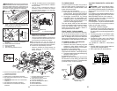
MOWER DRIVE BELT INSTALLATION
1. Install belt around both mandrel pulleys
(R) and around idler pulleys (S) as shown.
2. Install belt onto electric clutch pulley (M).
IMPORTANT: Check belt for proper routing
in all mower pulley grooves.
3. Reassemble R.H. and L.H. mandrel cov-
ers (Q). Securely tighten all screws.
4.
Engage belt tension rod (K) on locking
bracket (L).
CAUTION: Belt tension rod is spring load-
ed. Have a tight grip on rod and engage slowly.
5. Raise attachment lift lever to highest
position.
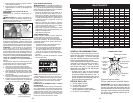
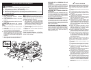
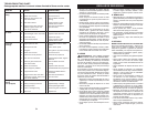
TO REPLACE MOTION DRIVE BELT
Park the tractor on level surface. En gage
parking brake. For as sis tance, there is a
belt installation guide decal on bottom side
of left footrest.
BELT REMOVAL -
1. Remove mower (See “TO RE MOVE
MOWER” in this section of manual).
C
D
F
G
H
J
A
B
NOTE: Observe entire motion drive belt and
position of all belt guides and keepers.
2. Disconnect clutch wire harness (A).
3. Remove anti-rotation link (B) on right side
of tractor.
4. Remove belt from stationary idler (C) and
clutching idler (D).
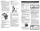
5. Pull belt slack toward rear of trac tor.
Carefully remove belt up wards from
trans mis sion input pulley and over cool-
ing fan blades (F).
6. Remove belt downward from engine
pulley and around electric clutch (G).
7. Slide belt toward rear of tractor, off the
steering plate (H) and remove from tractor.
BELT INSTALLATION -
1. Install new belt from tractor rear to front,
over the steering plate (H) and above
clutch brake pedal shaft (J).
2. Pull belt toward front of tractor and roll belt
around electric clutch and onto engine
pulley (G).
3. Pull belt toward rear of tractor. Carefully
work belt down around transmission
cooling fan and onto the input pulley (F).
Be sure belt is inside the belt keeper.
4. Install belt through stationary idler (C)
and clutch ing idler (D).
5. Reinstall anti-rotation link (B) on right
side of tractor. Tighten securely.
6. Reconnect clutch harness (A).
7. Make sure belt is in all pulley grooves
and in side all belt guides and keep ers.
8. Install mower (See “TO IN STALL MOW-
ER” in this sec tion of manual).
45
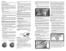
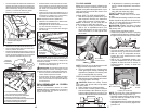
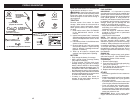
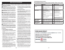
5. SI LA TIENE, INSTALE LA BARRA
ANTIBALANCEO (S)
Extremo Extremo Con
En 90° Arandela Integrada
BARRA ANTIBALANCEO (S)
Hacia El Hacia La Plataforma
Transeje De La Cortadora
De Césped
02965
A. Brazos De Suspensión Lateral De La
Cortadora De Césped
Q. Blindaje Deflector
Q
A
• Desde el lado derecho de la cortadora de
césped, inserte primero el extremo en 90° de la
barra antibalanceo (S) dentro del agujero de la
escuadra de transeje (T), ubicado cerca de la
rueda trasera izquierda adelante del transeje.
NOTA: Puede resultar útil usar una linterna.
S
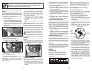
D
T
D. Escuadra Trasera Derecha De La
Cortadora De Césped
S. Barra Antibalanceo
T. Escuadra Transeje
NOTA: Dependiendo del modelo, la escuadra (T)
puede ser diferente de la que se ilustra, pero el
agujero para la barra antibalanceo estará en la
misma posición/ubicación.
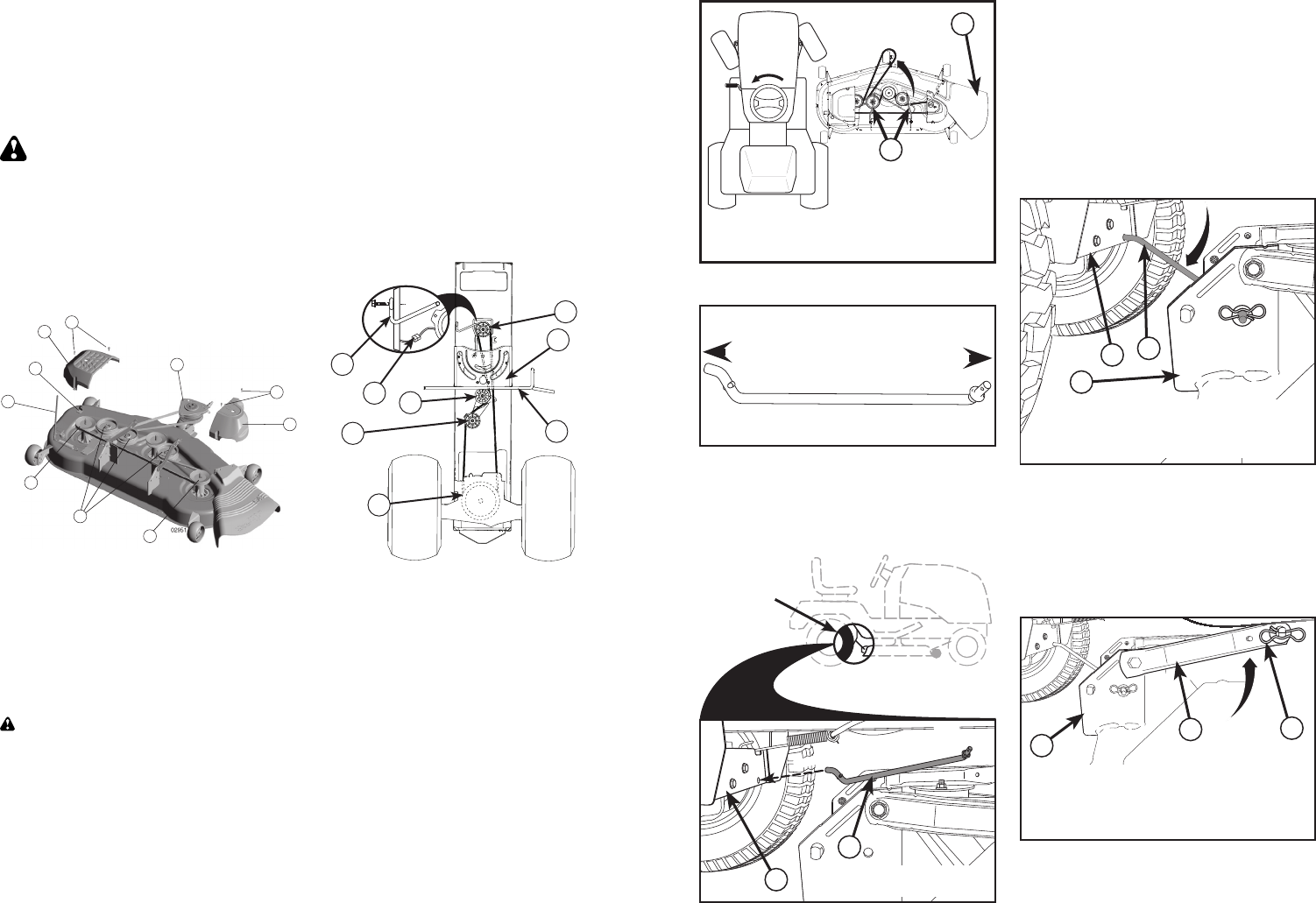
• Haga oscilar el extremo con la arandela
integrada de la barra antibalanceo (S) hacia
la escuadra de la plataforma de la cortadora
de césped en el lado derecho de la cortadora.
Inserte el extremo con la arandela integrada
de la barra en el agujero de la escuadra
trasera de la cortadora de césped (D). Mueva
la cortadora de césped según sea necesario
para insertar el extremo con la arandela
integrada de la barra en la escuadra trasera
de la cortadora de césped (D).
• Asegure con una arandela pequeña y un res-
orte de retención pequeño, como se ilustra.
6. INSTALE LOS BRAZOS DE SUSPENSIÓN
LATERAL DE LA CORTADORA DE CÉSPED
(A) EN EL CHASIS
• Ubique el agujero delantero del brazo de
suspensión lateral (A) sobre la chaveta en la
parte exterior del chasis del tractor y asegure
con una arandela grande y un resorte de
retención grande (B).
• Repita en el lado opuesto del tractor.
B
D
A
A. Brazos De Suspensión Lateral De La
Cortadora De Césped
B. Resorte De Retención
D. Escuadra Tras-Era Derecha De La
Cortadora De Césped
7. INSTALE LOS ESLABONES DE LEVAN-
TAMIENTO TRASEROS (C)
• Inserte el extremo de varilla del eslabón de
levantamiento trasero (C) dentro del agujero
(U) en el brazo de suspensión del eje de levan-
tamiento del tractor y haga oscilar el eslabón
hacia abajo hacia la cortadora de césped.
S
T
S. Barra Antibalanceo
T. Escuadra Transeje
Ubicación
De La Barra
Antibalanceo (S)
Escuadra De Transeje (T)
Ubicada Entre Las Ruedas
Coloque El Extremo En 90°
Coloque El Extremo En 90°
Dentro Del Agujero
Dentro Del Agujero