


24
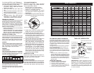
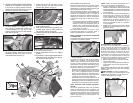
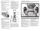
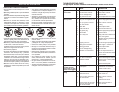
TO REPLACE MOTION DRIVE BELT
Park the tractor on level surface. En gage
parking brake. For as sis tance, there is a
belt installation guide decal on bottom side
of left footrest.
BELT REMOVAL -
1. Remove mower (See “TO RE MOVE
MOWER” in this section of manual).
NOTE: Observe entire motion drive belt
and position of all belt guides and keepers.
2. Remove belt from stationary idler (A) and
clutching idler (B).
3. Remove belt from centerspan idler (C).
6. Pull belt slack toward rear of trac tor.
Carefully remove belt up wards from
trans mis sion input pulley and over cool-
ing fan blades (D).
4. Remove belt downward from engine
pulley (E).
5. Slide belt toward rear of tractor, off the
steering plate (F) and remove from tractor.
A
B
C
D
E
F
G
BELT INSTALLATION -
1. Install new belt from tractor rear to front,
over the steering plate (F) and above
clutch brake pedal shaft (G).
2. Pull belt toward front of tractor and roll
belt onto engine pulley (E).
3. Pull belt toward rear of tractor. Carefully
work belt down around transmission
cooling fan and onto the input pulley (D).
Be sure belt is inside the belt keeper.
4. Install belt on centerspan idler (C).
5. Install belt through stationary idler (A)
and clutch ing idler (B).
6. Ensure belt is in all pulley grooves and
in side all belt guides and keep ers.
7. Install mower (See “TO IN STALL MOW-
ER” in this sec tion of manual).
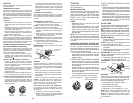
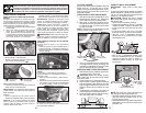
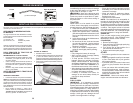
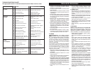
TO REPLACE MOWER BLADE DRIVE
BELT
The mower blade drive belt may be replaced
without tools. Park the tractor on level sur-
face. Engage parking brake.
BELT REMOVAL -
1. Remove mower from tractor (See “TO
REMOVE MOW ER” in this sec tion of
manual).
2. Work belt off both mandrel pulleys and
idler pulleys.
3. Pull belt away from mower.
BELT INSTALLATION -
1. Work belt around both mandrel pulleys
and idler pulleys
2. Ensure belt is in all pulley grooves and
inside all belt guides.
3. Install mower (See “To Install Mower” in
this section of this manual).
Idler
Pulleys
Mandrel
Pulley
Mandrel
Pulley
FRONT WHEEL TOE-IN/CAM BER
Your new tractor front wheel toe-in and
camber is set at the factory and is normal.
The front wheel toe-in and camber are not
adjustable. If damage has occurred to
affect the factory set front wheel toe-in or
camber, contact a Sears or other qualified
service center.
41
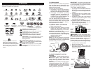
Nuestros tractores cumplen con los estándares de seguridad del American National Standard Institute.
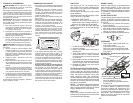
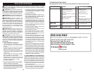
(A) PALANCA DEL LEVANTAMIENTO DEL AC-
CESORIO - Se usa para levantar, bajar y ajustar
el conjunto segador o los demás ac ce so rios
montados en su tractor.
(B) PEDAL DEL FRENO- Se usa para frenar el
tractor y para hacer arrancar el motor.
(C) PALANCA DEL FRENO DE ESTACIONA-
MIENTO - Ase gu ra el pedal del embrague/freno
en la posición del freno.
(D) CONTROL DE ACELERACIÓN/ESTRAN-
GULACIÓN - Se usa para hacer arrancar y
controlar la velocidad del mo tor.
(E) PALANCA DEL EMBRAGUE DEL AC-
CESORIO - Se usa para enganchar las cuchillas
segadoras, o los demás ac ce so rios montados
en su tractor.
(F) INTERRUPTOR DE IGNICIÓN - Se usa para
hacer arrancar o hacer parar el motor.
(G) SISTEMA DE FUNCIONAMIENTO HACIA
ATRÁS (ROS) EN POSICIÓN “ON” - Permite la
operación del conjunto segador o otro accesorio
accionado mientras que en revés.
(H) INTERRUPTOR DE LA LUZ - Enciende y
apaga las luces de lan te ras.
(J) PALANCA DE MANDO CRUCERO- Se utiliza
para fijar el movimiento hacia adelante del tractor
a la velocidad deseada sin apretar el pedal de
marcha atrás.
(K) PEDAL DE MARCHA ADELANTE - Se utiliza
para el movimiento del tractor hacia adelante.
(L) PEDAL DE MARCHA ATRÁS - Se utiliza para
el movimiento del tractor hacia atrás.
(M) CONTROL DE RUEDA LIBRE - Desengan-
cha la trans-misión para empujar o arrastrar.
FAMILIARICESE CON SU TRACTOR
LEA ESTE MANUAL DEL Y LAS REGLAS DE SEGURIDAD ANTES DE OPERAR SU TRACTOR
Compare las ilustraciones con su tractor para familiarizarse con las ubicaciones de los diversos
controles y ajustes. Guarde este manual para referencia en el futuro.
E
A
B
F
C
H
G
D
M
J
K
L