


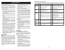

12
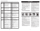
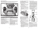
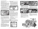
TO ADJUST GAUGE WHEELS
Gauge wheels are prop er ly ad just ed when
they are slight ly off the ground when mower
is at the desired cutting height in operating
position. Gauge wheels then keep the deck
in proper position to help prevent scalping
in most terrain conditions.
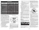
TO ADJUST MOWER CUT TING HEIGHT
The po si tion of the at tach ment lift le ver (A)
de ter mines the cut ting height.
• Put attachment lift lever in desired cut-
ting height slot.
The cutting height range is ap prox i mate ly
1" to 4". The heights are measured from
the ground to the blade tip with the engine
not running. These heights are approximate
and may vary depending upon soil condi-
tions, height of grass and types of grass
being mowed.
• The average lawn should be cut to ap-
proximately 2-1/2" during the cool sea-
son and to over 3" during hot months.
For healthier and better looking lawns,
mow often and after moderate growth.
• For best cutting performance, grass over
6" in height should be mowed twice. Make
the first cut relatively high; the second to
de sired height.
3. Repeat for all, installing gauge wheel
in same adjustment hole.
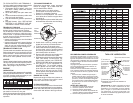
TO USE CRUISE CONTROL
The cruise control feature can be used for
forward travel only.
SYSTEM CHARACTERISTICS
The cruise control should only be used
while mowing or transporting on relatively
smooth, straight surfaces. Other con di tions
such as trimming at slow speeds may cause
the cruise control to dis en gage. Do not use
the cruise control on slopes, rough terrian
or while trimmimg or turning.
• With forward drive pedal (K) depressed to
desired speed, pull cruise control lever (J)
up and hold while lifting your foot off the
pedal, then release the lever.
To disengage the cruise control, depress the
brake pedal or tap on forward drive pedal.
A
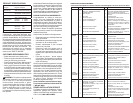
TO OPERATE MOWER
Your tractor is equipped with an operator
presence sensing switch. Any attempt
by the operator to leave the seat with the
engine running and the attachment clutch
engaged will shut off the engine. You must
remain fully and centrally positioned in the
seat to prevent the engine from hesitating or
cutting off when operating your equipment
on rough, rolling terrain or hills.
1. Select desired height of cut with attach-
ment lift lever.
2. Start mower blades by engaging at tach-
ment clutch control.
TO STOP MOWER BLADES
Disengage at tach ment clutch con trol.
CAUTION: Do not operate the mower
without either the en tire grass catcher, on
mowers so equipped, or the deflector shield
(S) in place.
NOTE: Adjust gauge wheels with tractor on
a flat level surface.
1. Adjust mower to desired cutting height
(See “TO AD JUST MOWER CUT TING
HEIGHT” in this sec tion of manual).
2. With mower in desired height of cut po si-
tion, gauge wheels should be assembled
so they are slightly off the ground. In stall
gauge wheel in ap pro pri ate hole. Tighten
se cure ly.
S
53
E
F
H
J
M
A
B
C
D
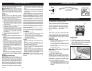
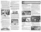
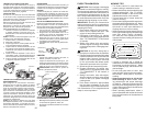
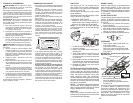
4. Realice el mismo procedimiento en el otro
lado del tractor.
5. FIJE LAS PIEZAS DE PROPULSIÓN POS-
TERIORES (C) – Levante la parte posterior
de la cortadora, ubique la ranura de la pieza
de unión (D) por encima de la clavija que hay
en la barra posterior de la cortadora y fíjela
con una arandela y un resorte de contención.
6. FIJE LA PIEZA DE UNIÓN ANTERIOR (E)
– Trabaje por el lado izquierdo del tractor.
Introduzca el extremo de la barra de la pieza
de unión por el orificio anterior de la barra de
suspensión anterior del tractor (F).
7. Introduzca el otro extremo de la pieza de
unión (E) en el orificio que se encuentra en
la barra anterior de la cortadora (H), y fíjelo
por medio de una arandela y un resorte de
contención (J).
8. Retire el resorte del cable del embrague (Q)
del brazo del engranaje (R).
9. Retire el resorte de sujeción (K), deslice la
abrazadera (L) hasta quitarla, y saque a
presión la guía de la caja (P) hasta que se
salga del soporte.
10. Instale la correa pasándola por encima de la
polea del motor (M) y fijadors de la correa (G).
IMPORTANTE: Verifique que la correa encaje
bien en todas las ranuras de las poleas de la
cortadora.
11. Suba la palanca elevadora a la posición de
más arriba.
12. Si es necesario, ajuste las rueditas del calibre
antes de poner en funcionamiento la corta-
dora, como se ilustra en el capítulo de Manejo
de este manual.
E
F
C
G
Q
R
D
K
G
P
B
L
M
A