


REPAIR PARTS
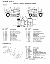
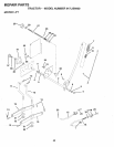
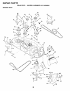
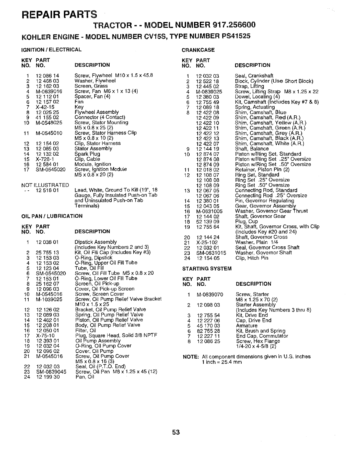
TRACTOR - - MODEL NUMBER 917.256600
KOHLER ENGINE - MODEL NUMBER CV15S, TYPE NUMBER PS41525
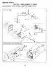
IGNITION / ELECTRICAL CRANKCASE
KEY PART KEY PART
NO. NO. DESCRIPTION NO. NO. DESCRIPTION
1 1208614 Screw, Flywheel M10 x 1.5 x45.8 1 1203203
2 1246803 Washer, Flywheel 2 1252218
3 1216203 Screen, Grass 3 1244502
4 M-0639016 Screw, Fan M6 x 1 x 13 (4) 4 M-0839025
5 1211201 Spacer, Fan (4) 5 1238003
6 1215702 Fan 6 12 755 49
7 X-42-15 Key 7 12 089 18
8 12 025 25 Flywheel Assembly 8 12 422 08
9 41 155 02 Connector (4 Contact) 12 422 09
10 M-0548025 Screw, Stator Mounting 12 422 10
M5 x 0.8 x 25 {2) 12 422 11
11 M-0545010 Screw, Stator Harness Clip 12 422 12
M5 x0.8x 10(2) 12422 13
12 12 154 02 Clip, Stator Harness 12 422 07
13 12 085 03 StatorAssembly 9 12 144 19
14 1213202 SparkP_ug 10 1287407
15 X-728-1 Clip, Cable 12 874 08
16 12 584 01 Module, Ignition 12 874 09
17 SM-0545020 Screw, Ignition Module 11 12 018 02
M5 x0.8 x20 (2) 12 1210807
12 108 08
NOT ILLUSTRATED 12 108 09
- - 12 518 01 Lead, White, Ground To Kill (19", 18 13 12 067 05
Gauge, Fully Insulated Push-on Tab 12 067 06
and Uninsulated Push-on Tab 14 12 380 01
Terminals) 15 12 043 05
16 M-0631005
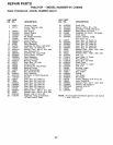
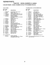
OIL PAN / LUBRICATION 17 12 144 02
18 52 139 O9
KEY PART 19 1275564
NO. NO. DESCRIPTION
12 038 01
2 25 755 13
3 12 153 03
4 12 153 02
5 12 123 04
6 SM-0545020
7 12 153 01
8 25 162 07
9 12 096 03
10 M-0545016
11 M-1039025
12 12 126 02
13 12 089 03
14 12 462 01
15 12208 01
16 12 050 01
17 X-75-10
18 12 39301
19 12 032 04
20 12 096 02
21 M-0545016
22 12 032 03
23 SM-0839045
24 12 199 30
Dipstick Assembly
(Includes Key Numbers 2 and 3)
Kit, Oi! Fill Cap (Includes Key #3)
O-Ring, Dipstick
O-Ring, Upper Oil Fill Tube
Tube, Oil Fill
Screw, Oil Fill Tube M5 x 0.8 x 20
O-Ring, Lower Oil Fill Tube
Screen, Oil Pick-up
Cover, Oil Pick-up Screen
Screw, Screen Cover
Screw, Oil Pump Relief Valve Bracket
M10x 1.5 x25
Bracket, Oil Pump Relief Valve
Spring, Oil Pump Relief Valve
Piston, Oil Pump Relief Valve
Body, Oil Pump Relief Valve
Filter, Oil
Plug, Square Head, Solid 3/8 NPTF
Oil Pump Assembly
O-Ring, Oil Pump Cover
Cover, Oil Pump
Screw, Oil Pump Cover
M5 x 0.8 x 16 (3)
Seal, Oil (P.T.O. End)
Screw, Oil Pan M8 x 1.25 x45 (12)
Pan, Oil
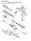
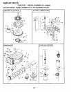
20 12 144 24
21 X-25-102
22 12 032 01
23 SM-0631015
24 12 154 05
Seal, Crankshaft
Block, Cylinder (Use Short Block)
Strap, Lifting
Screw, Lifting Strap M8 x 1.25 x 22
Dowel, Locating (4)
Kit, Camshaft (Includes Key #7 & 8)
Spring, Actuating
Shim, Camshaft, Blue
Shim, Camshaft, Red (A.R.)
Shim, Camshaft, Yellow (A.R.)
Shim, Camshaft, Green (A.R.)
Shim, Camshaft, Grey (A.R.)
Shim, Camshaft, Black (A.R.)
Shim, Camshaft, White (A.R.)
Shaft, Balance
Piston w/Ring Set, Standard
Piston w/Ring Set .25" Oversize
Piston w/Ring Set .50" Oversize
Retainer, Piston Pin (2)
Ring Set, Standard
Ring Set .25 Oversize
Ring Set .50" Oversize
Connecting Rod, Standard
Connecting Rod .25" Oversize
Pin, Governor Regulating
Gear, Governor Assembly
Washer, Governor Gear Thrust
Shaft, Governor Gear
Plug, Cup
Kit, Shaft, Governor Cross, with Clip
(Includes Key #20 and 24)
Shaft, Governor Cross
Washer, Plain 1/4
Seal, Governor Cross Shaft
Washer, Governor Shaft
Clip, Hitch Pin
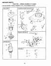
STARTING SYSTEM
KEY PART
NO. NO.
DESCRIPTION
3
4
5
6
7
8
M-0839070
12 098 03
12 755 54
12 227 06
45 170 03
82 755 28
12 22711
12 086 25
Screw, Starter
M8 x 1.25 x 70 (2)
Starter Assembly
(Includes Key Numbers 3 thru 8)
Kit, Drive End
Cap, Drive End
Armature
Kit, Brush and Spring
End Cap, Commutator
Screw, Hex Flange
1/4-20 x 4-5/8 (2)
NOTE: All component dimensions given in U.S. inches
1 inch = 25.4 mm
53