


SERVICE AND ADJUSTMENTS
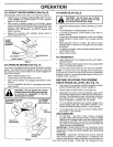
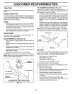
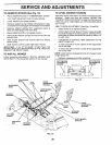
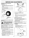
TO REMOVE MOWER (See Fig. 18)
= Place attachment clutch in "DISENGAGED" position.
- Turn height adjustment knob to lowest setting.
= Lower mower to its lowest position.
Remove retainer spring holding anti-swaybar to chas-
sis bracket and disengage anti-swaybar from bracket.
Remove retainer springs from suspension arms at
deck and disengage arms from deck.
• Raise attachment lift to its highest position.
• Remove two retainer springs from each front link and
remove links.
° Slide mower forward and remove belt from electric
clutch pulley.
° Slide mower out from under right side of tractor.
IMPORTANT: IFAN ATTACHMENT OTHER THAN THE
MOWER DECK ISTO BE MOUNTED ON THE TRACTOR,
REMOVE THE FRONT LINKS.
TO INSTALL MOWER
Follow procedure described in "INSTALL MOWER AND
DRIVE BELT" in the Assembly section of this manual.
TO LEVEL MOWER HOUSING
Adjust the mower while tractor is parked on level ground or
driveway. Make sure tires are properly inflated (See
"PRODUCT SPECIFICATIONS" on page 3of this manual).
If tires are over or underinflated, you will not properly adjust
your mower.
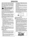
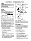
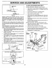
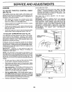
SIDE-TO-SIDE ADJUSTMENT (See Figs. 19 and 20)
• Raise mower to its highest position.
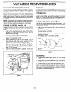
o Atthe midpoint of both sidesof mower, measure height
from bottom edge of mower to ground. Distance "A" on
both sides of mower should be the same or within 1/4"
of each other.
If adjustment is necessary, make adjustment on one
side of mower only.
= To raise one side of mower, tighten lift link adjustment
nut on that side.
- To lower one side of mower, loosen lift link adjustment
nut on that side.
NOTE: Each full turn of adjustment nut will change mower
height about 1/8".
Recheck measurements after adjusting.
BOTTOM EDGE BOTTOM EDGE
OF MOWER TO OF MOWER TO
GROUND GROUND
GROUND LINE
ADJUSTMENT
NUTS
SUSPENSION
ARMS
CHASSIS
LIFT
LINKS
FRONT
SUSPENSION
BRACKET
FIG. 19
//
FRONT
SUSPENSION
BRACKET
RETAINER
SPRING
ANTI-SWAY
BAR RETAINER
RETAINER
SPRINGS
FRONT MOWER
BRACKET
FIG. 18
2O