


SERVICE AND ADJUSTMENTS
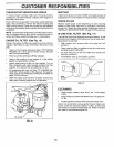
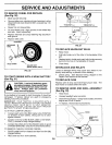
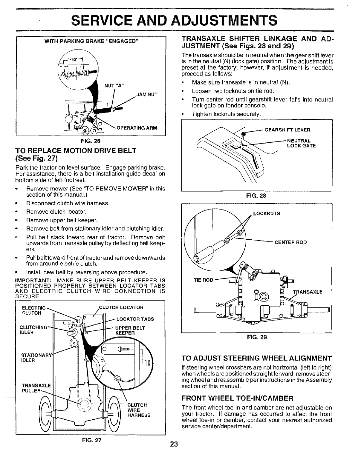
WITH PARKING BRAKE "ENGAGED"
NUT "A"
JAM NUT
"-OPE.AT,NGAR,,
FIG. 26
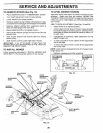
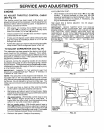
TO REPLACE MOTION DRIVE BELT
(See Fig. 27)
Park the tractor on level surface. Engage parking brake.
For assistance, there is a belt installation guide decal on
bottom side of left footrest.
• Remove mower (See "TO REMOVE MOWER" in this
section of this manual.)
= Disconnect clutch wire harness.
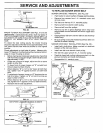
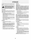
TRANSAXLE SHIFTER LINKAGE AND AD-
JUSTMENT (See Figs. 28 and 29)
The transaxle should be in neutral when the gear shift lever
is in the neutral (N) (lock gate) position. The adjustment is
preset at the factory; however, if adjustment is needed,
proceed as follows:
• Make sure transaxle isin neutral (N).
• Loosen two Iocknuts on tie rod.
• Turn center rod until gearshift lever falls into neutral
lock gate on fender console.
• Tighten Iocknuts securely.
GEARSHIFT LEVER
LOCK GATE
FIG. 28
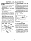
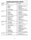
° Remove clutch Iocator.
,, Remove upper belt keeper.
,, Remove belt from stationary idler and clutching idler.
,, Pull belt slack toward rear of tractor. Remove belt
upwards from transaxle pulley by deflecting belt keep-
ers.
,, Pull belt toward front oftractor and remove downwards
from around electric clutch.
° Install new belt by reversing above procedure.
IMPORTANT: MAKE SURE UPPER BELT KEEPER IS TIEROD
POSITIONED PROPERLY BETWEEN LOCATOR TABS
AND ELECTRIC CLUTCH WIRE CONNECTION IS
[ E'ECTR,C-- CLUTCH'OCA
| CLUTCHING"Jrt-...,.,_ '_,,,"_ _ UPPER I
| TRANSAXLEII ,--J1--'=_
/ PUL'E'€--'--L[1 i i 1 II-
CLUTCH LOCATOR
LOCATOR TABS
UPPER BELT
FiG. 29
__
TRANSAXLE
LOCKNUTS
CENTER ROD
TO ADJUST STEERING WHEEL ALIGNMENT
If steering wheel crossbars are not horizontal (left to right)
when wheels are positioned straight forward, remove steer-
_ ing wheel and reassemble per instructions in the Assembly
section of this manual.
........................................... FRONTWHEEL TOE-IN/CAMBER
The front wheel toe-in and camber are not adjustable on
your tractor. If damage has occurred to affect the front
wheel toe-in or camber, contact your nearest authorized
service center/department.
CLUTCH
WIRE
HARNESS
FIG. 27
23