


5. TIRE CARE
a. Maintain tire pressure in front tires at 14 PSi and rear
tires at 12 PSi
b Keep tires free of gasoline, oil. or insect control chemio
cals which can destroy rubber
c Avoid stumps, stones, deep ruts and other hazards that
may cause tire damage
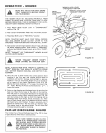
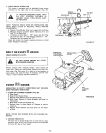
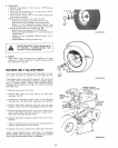
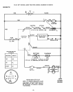
d. Removing front wheel for tire repair (Fig. 35)
-- Block up front axle securely° Puit off Dust Cap.
-- Remove Klip Ring and Washer and remove wheel°
-- Repair tire and reassembfeo Replace Washer, snap
Klip Ring securely in axle groove, RepIace Dust Cap
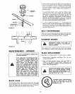
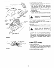
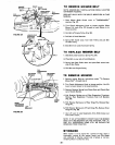
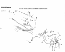
e Removing rear wheel for tire repair (Fig 36)..
-- Block up rear axle securely. P011 off Dust Cap
-- Remove E-Ring and Washers (1 to 3 as required) and
remove wheel
-- Repair tire and reassemble, Replace Square K.ey in
Axle Shaft
.- Replace Washers, E-Ring and Dust Cap
KL1P RING
DUST
CAP
FIGURE 35
WHEN MOUNTING TIRES, BEADS MUST
BE SEATED. OVERINFLATION CAN
CAUSE A FATAL EXPLOSION.
6. FINISH
Keep tractor finish and seat free of gasoline, oil, insect
chemicals or battery electrolyte Protect painted surfaces
with automotive type wax
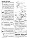
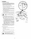
MOWER BELT AGJUSTMENT
Your tractor has been manufactured with the ability to re-ad-
just mower drive belt to provide you with longer belt life,
If the Mower Clutch Lever (Fig, 37) travels 3-I/2" up the slot
in the dash before spring tension resistance is evident, adjust-
ment is necessary. NOTE: CHECK FOR PROPER SPRING
TENSION WITH ENGINE OFF AND LIFT LEVER IN HIGH-
EST POSITION
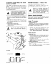
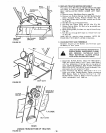
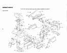
1. Remove mower deck from tractor
2 Remove Cotter Pins from both sides of the Rock Shaft
Assembly (Fig. 38)
37 Loosen the4 Locknuts on the RH and LH Pivot Brackets
(Fig, 38) only unti! Rock Shaft Assembly can be removed
4 Remove Rock Shaft Assembly from R H. and L H Pivot
Brackets NOTE: DO NOT DISASSEMBLE BRAKE ROD
5, Remove Extension Spring from lower hole (original posi-
tion) in Rock Shaft Assembly and insert in upper hole in
Rock Shaft Assembly {Fig. 38 - Inset)
6 Replace Rock Shaft Assembly between R H and L H Pivot
Brac ket s
7 Tighten Locknuts securely making sure Carriage Bolts are
seated in square holes of mower housing.
8, Replace Cotter Pins on both sides of Rock Shaft Assembly
NOTE: WHEN INSTALLING A NEW BELT, EXTENSION
SPRING MUST BE RETURNED TO LOWER HOLE (ORIGI-
NAL POSITION) ON ROCK SHAFT ASSEMBLY.
DUST
CAP
E _IING
WASHERS
DEPTH
ADJUSTMENT
KNOB
,\
FIGURE 36
MOWER CLUTCH
LEVER "DISENGAGED*'
POSITION
IEST"
LIFT LEVER
*'LOWEST'*
POSITION
FIGURE 37
• !9.,