


LY
i iill Ill. I / I / / I Illllll III,
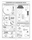
Your new tractor has been assembled at the factory with exception of those parts left unassembled for shipping purposes.
To ensure safe and proper operation of your tractor all parts and hardware you assemble must be tightened securely. Use
the correct tools as necessary to insure proper tightness°
TOOLS REQUIRED FOR ASSEMBLY
A socket wrench set will make assembly easier.. Standard
wrench sizes are listed_
(1) 5/16" wrench
(2) 7/16" wrenches
(1) 1/2" wrench
(1) 9/16" wrench
(1) 3/4" Socket w/drive rachet
Phillips Screwdriver
Tire pressure gauge
Utility knife
When right or left hand is mentioned in this manual, it
means when you are in the operating position (seated
behind the steering wheel).
TO REMOVE TRACTOR FROM CARTON
UNPACKCARTON
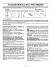
• Remove all accessible loose parts and parts cartons
from carton (See page 6).
. Cut, from top to bottom, along lines on all four corners
of carton, and lay panels flat..
° Check for any additional loose parts or cartons and
remove,
BEFORE ROLLING TRACTOR OFF SKaD
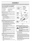
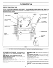
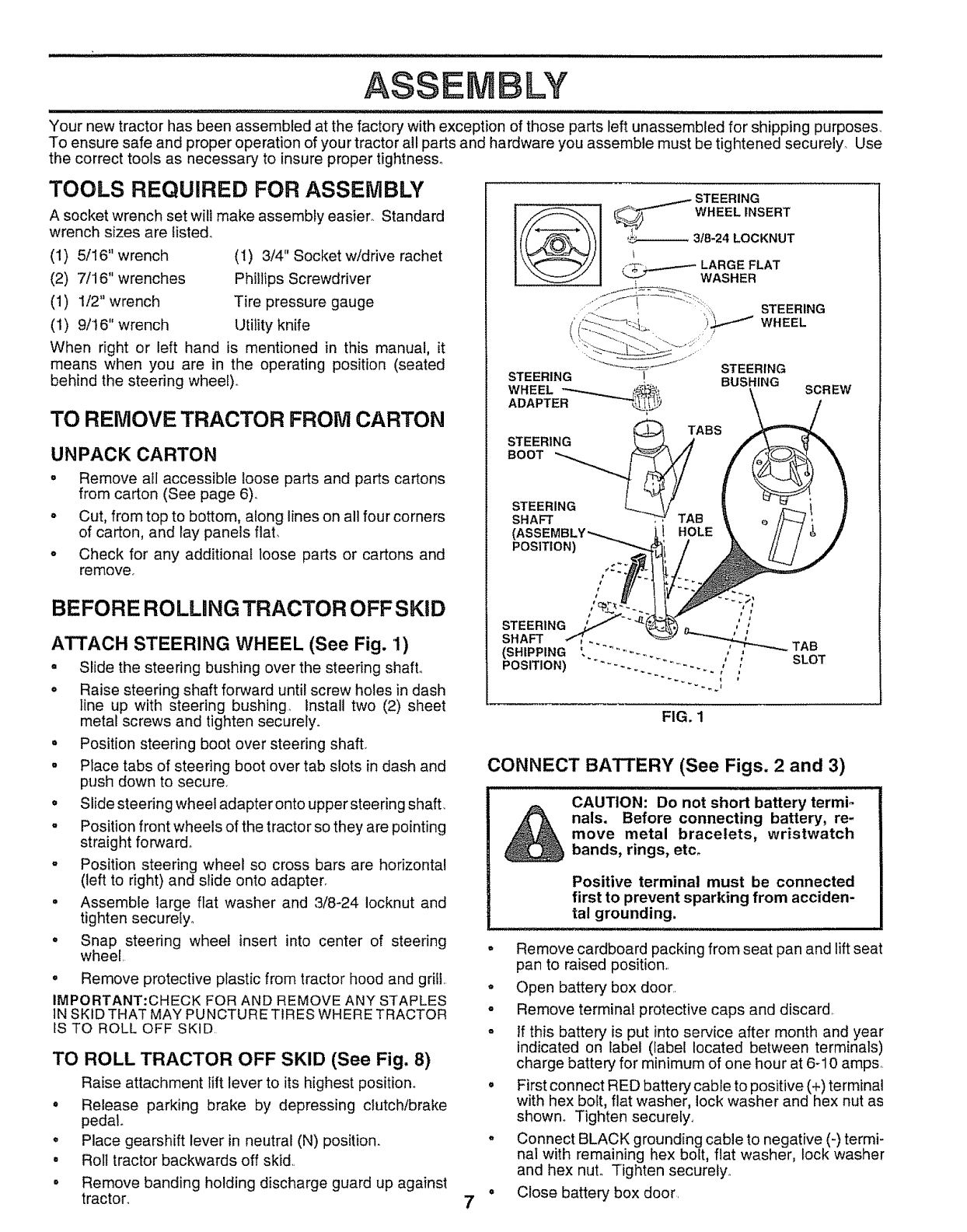
ATTACH STEERING WHEEL (See Fig, 1)
o Slide the steering bushing over the steering shaft°
° Raise steering shaft forward until screw holes in dash
line up with steering bushing, Install two (2) sheet
metal screws and tighten securely°
• Position steering boot over steering shaft
. Place tabs of steering boot over tab slots in dash and
push down to secure.
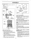
° Slide steering wheel adapter onto upper stee ring shaft.
- Position front wheels of the tractor so they are pointing
straight forward°
o Position steering wheel so cross bars are horizontal
(left to right) and slide onto adapter_
= Assemble large flat washer and 3/8-24 iocknut and
tighten securely.
° Snap steering wheel insert into center of steering
wheel.
= Remove protective plastic from tractor hood and grill..
IMPORTANT:CHECK FOR AND REMOVE ANY STAPLES
IN SKiD THAT MAY PUNCTURE TIRES WHERE TRACTOR
tS TO ROLL OFF SKiD
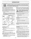
TO ROLL TRACTOR OFF SKID (See Fig. 8)
Raise attachment lift lever to its highest position°
° Release parking brake by depressing clutch/brake
pedal
o Place gearshift lever in neutral (N) position.
° Roll tractor backwards off skid,,
• Remove banding holding discharge guard up against
tractor,
STEERING
_ WHEEL INSERT
.... 3t8-24 LOCKNUT
_ LARGE FLAT
WASHER
STEERING
STEERING
)_ WHEEL
STEERING
I BUSHING
SCREW
TABS
STEERING _ A
,oo
STEERING _ //
SHAFT _ TAB
HOLE
POSITION)
STEERING
SHAFT
(SHIPPING
POSITION)
FIG. 1
7
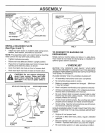
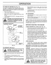
CONNECT BATTERY (See Figs. 2 and 3)
CAUTION: Do not short battery termio
_ nals. Before connecting battery, re-
move metal bracelets, wristwatch
bands, rings, etco
Positive terminal must be connected
first to prevent sparking from acciden-
tal grounding.
• Remove cardboard packing from seat pan and lift seat
pan to raised position,.
° Open battery box door.
o Remove terminal protective caps and discard.
o If this battery is put into service after month and year
indicated on label (label located between terminals)
charge battery for minimum of one hour at 6-10 amps.
° First connect RED battery cable to positive (+) terminal
with hex bolt, flat washer, lockwasher and hex nut as
shown° Tighten securely..
° Connect BLACK grounding cable to negative (-)termi-
nal with remaining hex bolt, fiat washer, lock washer
and hex nut° Tighten securely.
° Close battery box door