


ERVmCEAN
ADJUSTMENTS
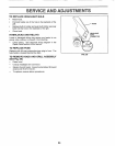
TO ADJUST STEERING WHEEL ALIGNMENT
If steering wheel crossbars are not horizontal (left to right)
when wheels are positioned straightforward, remove steer-
ing wheel and reassemble per instructions in the Assembly
section of this manual
FRONT WHEEL TOE-IN/CAMBER
The front wheel toe-in and camber are not adjustable on
your tractor, if damage has occurred to affect the front
wheel toe-in or camber, contact your nearest authorized
service center/department,,
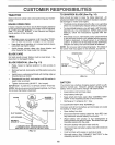
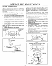
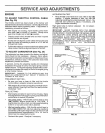
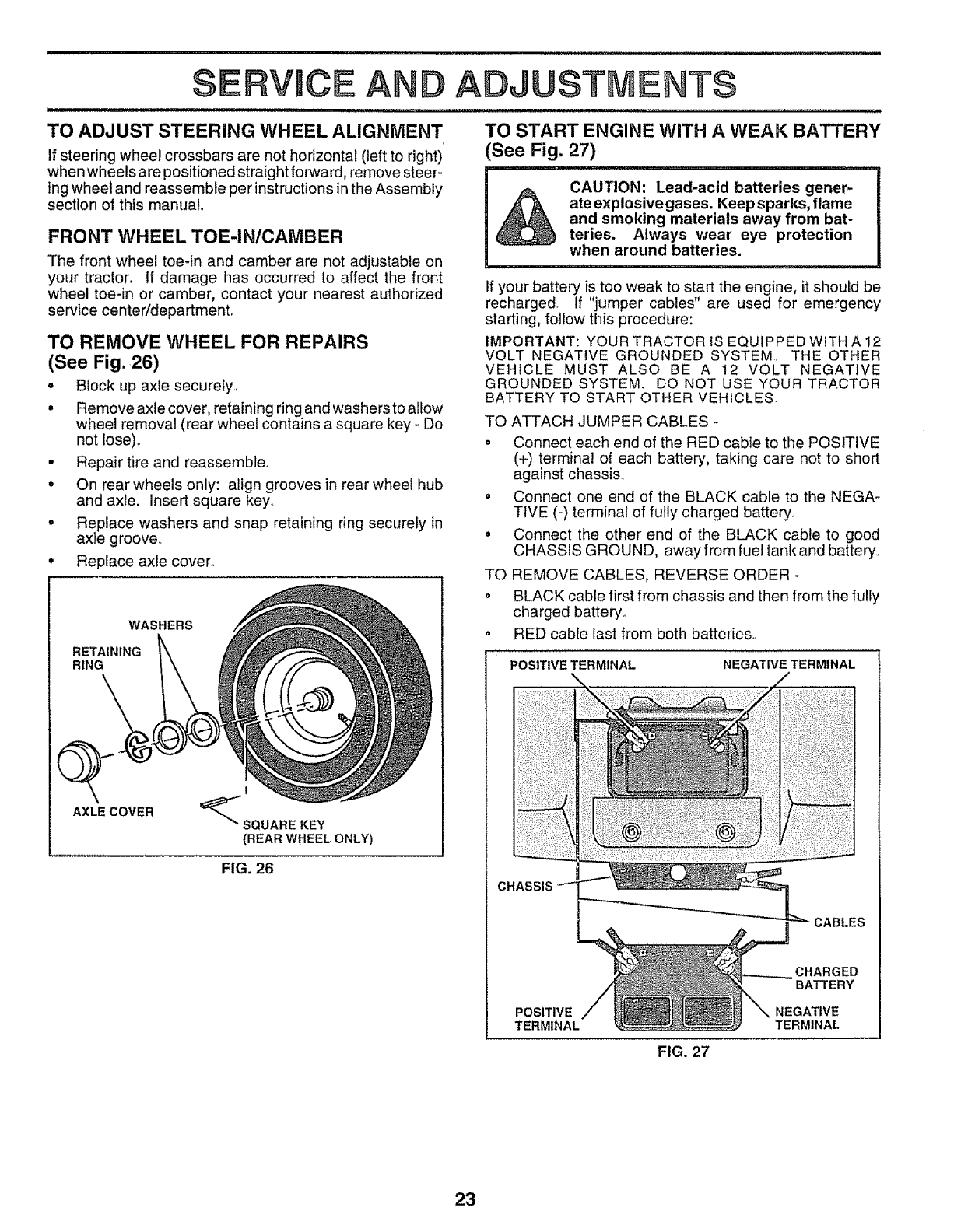
TO REMOVE WHEEL FOR REPAIRS
(See Fig. 26)
• Block up axle secure{y,
° Remove axle cover, retaining ring and washers to allow
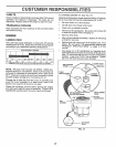
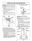
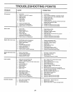
TO START ENGINE WITH A WEAK BATTERY
See Fig. 27)
_u=_,,, _
CAUTION; Lead-acid batteries gener-
ate explosive gases. Keep sparks, flame
and smoking materials away from bat-
teries. Always wear eye protection
when around batteries.
If your battery is too weak to start the engine, it should be
recharged° If "jumper cables" are used for emergency
starting, follow this procedure:
IMPORTANT: YOUR TRACTOR IS EQUIPPED WITH A 12
VOLT NEGATIVE GROUNDED SYSTEM THE OTHER
VEHICLE MUST ALSO BE A 12 VOLT NEGATIVE
GROUNDED SYSTEM, DO NOT USE YOUR TRACTOR
BATTERY TO START OTHER VEHICLES_
wheel removal (rear wheel contains a square key - Do
not Iose)_
• Repair tire and reassemble°
° On rear wheels only: align grooves in rear wheel hub
and axle. Insert square key.
• Replace washers and snap retaining ring securely in
axle groove.
• Replace axle cover.
WASHERS
RETAINING
RING
AXLE COVER
1
_"SQUARE KEY
(REAR WHEEL ONLY)
FIG. 26
TO ATTACH JUMPER CABLES -
o Connect each end of the RED cable to the POSITIVE
(+) terminal of each battery, taking care not to short
against chassis,
= Connect one end of the BLACK cable to the NEGA-
TIVE (-) terminal of fully charged battery_
° Connect the other end of the BLACK cable to good
CHASSIS GROUND, away from fuel tank and battery
TO REMOVE CABLES, REVERSE ORDER -
= BLACK cable first from chassis and then from the fully
charged battery.
° RED cabte last from both batteries,
POSITIVE TERMINAL NEGATIVE TERMINAL
CHASSIS
CABLES
CHARGED
BATTERY
POSITIVE NEGATIVE
TERMINAL TERMINAL
FIG. 27
23