


REPARR ,PARTS
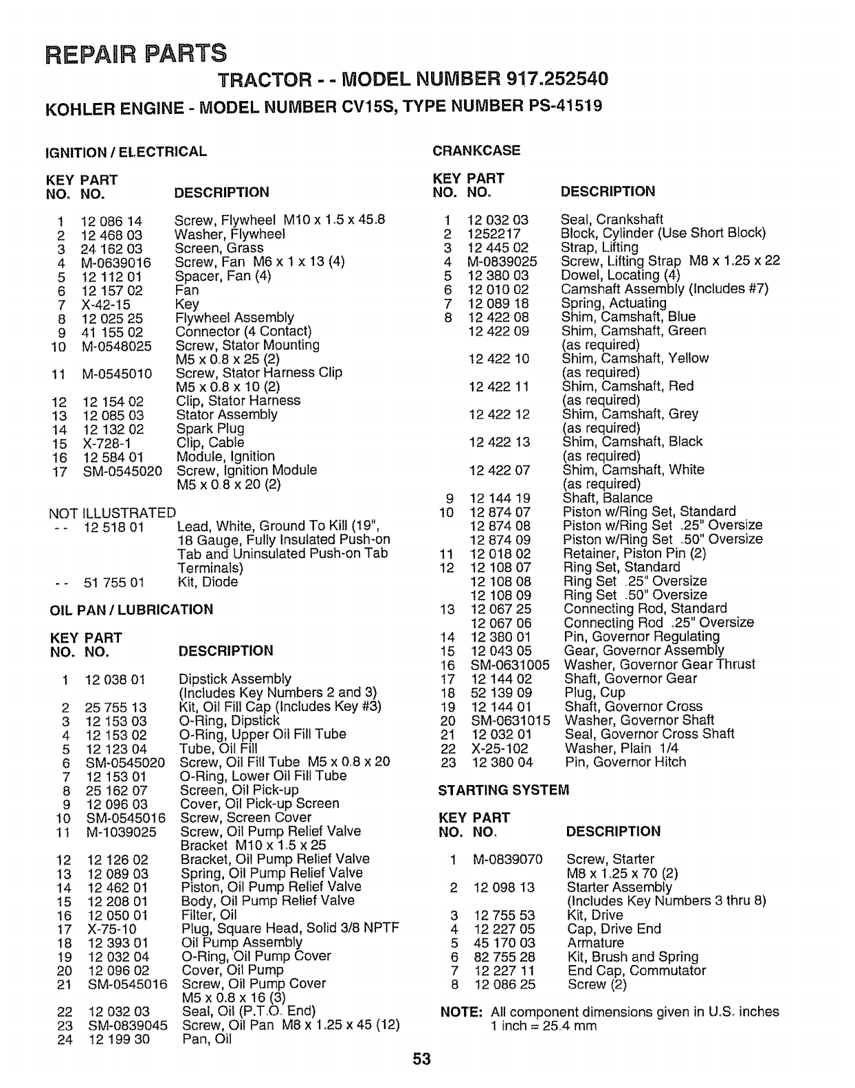
TRACTOR - - MODEL NUMBER 9!7.252540
KOHLER ENGINE - MODEL NUMBER CV15S, TYPE NUMBER PS-41519
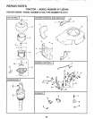
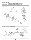
IGNITION 1ELECTRICAL
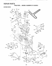
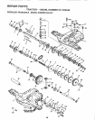
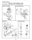
CRANKCASE
KEY PART KEY PART
NO. NO. DESCRIPTION NO. NO. DESCRIPTION
1 12 086 14 Screw, Flywheel Mt0 x 1.5 x 45.8
2 12 468 03 Washer, Flywheel
3 24 162 03 Screen, Grass
4 M-0639016 Screw, Fan M6 x 1 x 13 (4)
5 12 112 01 Spacer, Fan (4)
6 1215702 Fan
7 X_42-15 Key
8 12 025 25 Flywheel Assembly
9 41 155 02 Connector (4 Contact)
10 M-0548025 Screw, Stator Mounting
M5 x &8 x 25 (2)
11 M-0545010 Screw, Stator Harness Clip
M5 x 0.8 x 10 (2)
12 12 154 02 Clip, Stator Harness
13 12 085 03 Stator Assembly
14 12 132 02 Spark Plug
15 X-728-1 Clip, Cable
'16 12 584 01 Module, Ignition
17 SM-0545020 Screw, Ignition Module
M5 x 0.8 x 20 (2)
ILLUSTRATED
12 518 01 Lead, White, Ground To Kill (19",
18 Gauge, Fulty Insulated Push-on
Tab and Uninsulated Push-on Tab
Terminals)
51 755 01 Kit, Diode
NOT
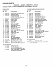
OIL PAN / LUBRICATION
DESCRIPTION
KEY PART
NO. NO.
12 038 01
2 25 755 13
3 12 153 03
4 12 15302
5 12 123 04
6 SM-0545020
7 12 15301
8 25 162 07
9 12 096 03
10 SM-0545016
11 M-1039025
12 12 126 02
13 !2 089 03
14 124620'1
15 12 2O8 01
16 12 050 01
17 X-75-10
18 12 393 01
t9 12 032 04
20 12 096 02
21 SM-0545016
Dipstick Assembly
(includes Key Numbers 2 and 3)
Kit, Oil Fill Cap (Includes Key #3)
O-Ring, Dipstick
O-Ring, Upper Oil Fill Tube
Tube, Oil Fill
Screw, Oil Fill Tube M5 x 0..8x 20
O-Ring, Lower Oil Fill Tube
Screen, Oil Pick-up
Cover, Oil Pick-up Screen
Screw, Screen Cover
Screw, Oit Pump Relief Valve
Bracket M10 x 1.5 x 25
Bracket, Oil Pump Relief Valve
Spring, Oil Pump Relief Valve
Piston, Oil Pump Relief Valve
Body, Oil Pump Relief Valve
Filter, Oil
Plug, Square Head, Solid 3/8 NPTF
Oil Pump Assembly
O-Ring, Oil Pump Cover
Cover, Oil Pump
Screw, Oil Pump Cover
M5 x 0.8 x 16 (3)
Seal, Oil (P.T_O.. End)
Screw, Oil Pan M8 x 1.25 x 45 (12)
Pan, Oil
22 12 032 03
23 SM-0839045
24 12 199 30
1
2
3
4
5
6
7
8
12 032 03
1252217
12 445 02
M-0839025
12 380 03
!2 010 02
12 089 18
t2 422 08
12 422 09
!2 422 10
12 422 11
12 422 12
12 422 13
12 422 07
9 1214419
10 12 874 07
12 874 08
12 874 09
11 12 018 O2
12 12 !08 07
12108 08
12108 09
13 12 O67 25
12 067 06
14 12 380 01
15 12 043 05
16 SM-0631005
17 12 144 02
18 52 139 09
19 12144 01
20 SM-0631015
21 12 032 01
22 X-25-102
23 12 380 04
Seal, Crankshaft
Block, Cylinder (Use Short Block)
Strap, Lifting
Screw, Lifting Strap M8 x 1o25x 22
Dowel, Locating (4)
Camshaft Assembly (Includes #7)
Spring, Actuating
Shim, Camshaft, Blue
Shim Camshaft, Green
(as required)
Shim, Camshaft, Yellow
(as required)
Shim, Camshaft, Red
(as required)
Shim, Camshaft, Grey
(as required)
Shim, Camshaft, Black
(as required)
Shim, Camshaft, White
(as required)
Shaft, Balance
Piston w/Ring Set, Standard
Piston w/Ring Set _25" Oversize
Piston w/Ring Set .50" Oversize
Retainer, Piston Pin (2)
Ring Set, Standard
Ring Set ..25" Oversize
Ring Set .50" Oversize
Connecting Rod, Standard
Connecting Rod ..25"Oversize
Pin, Governor Regulating
Gear, Governor Assembly
Washer, Governor Gear Thrust
Shaft, Governor Gear
Plug, Cup
Shaft, Governor Cross
Washer, Governor Shaft
Seal, Governor Cross Shaft
Washer, Plain 1/4
Pin, Governor Hitch
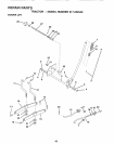
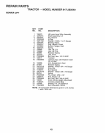
STARTING SYSTEM
KEY PART
NO. NO, DESCRIPTION
1 M-0839070 Screw, Starter
M8 x 1.25 x 70 (2)
2 12 098 13 Starter Assembly
(Includes Key Numbers 3 thru 8)
3 12 755 53 Kit, Drive
4 12 227 05 Cap, Drive End
5 45 '170 03 Armature
6 82 755 28 Kit, Brush and Spring
7 I2 227 11 End Cap, Commutator
8 12 086 25 Screw (2)
NOTE: All component dimensions given in U.S. inches
1 inch = 25.4 mm
53