


REPAIR
ADJUSTMENT
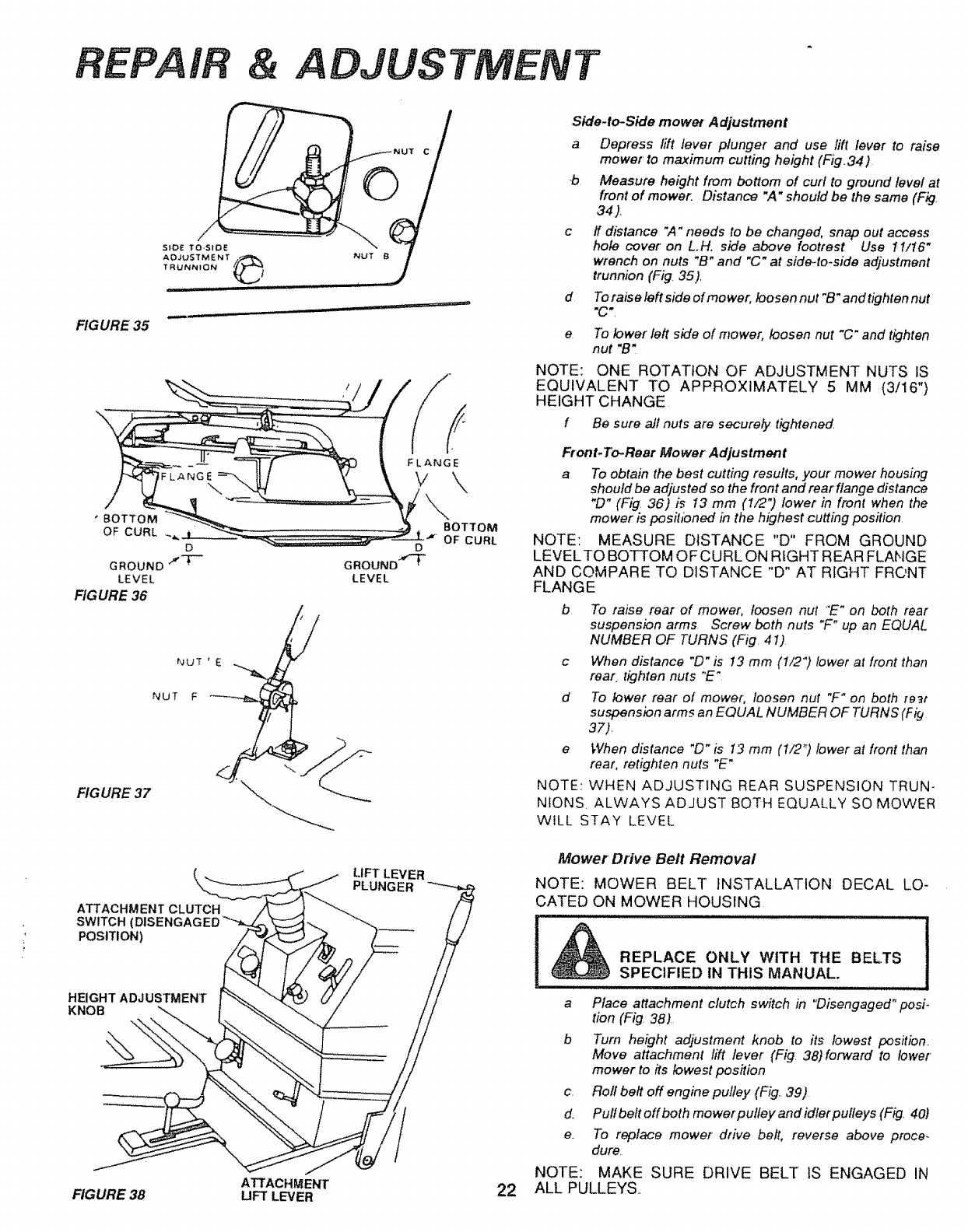
FIGURE" 35
SiDE TO.SiDE
AOJUSTMENT
TRUNNION
IIII IIII
C
iiii _
' BOTTOM
OF CURL _._
D
GROUND J-i--
LEVEL
FIGURE 36
D
GROUND-_"T"
LEVEL
FIGURE 37
ATTACHMENT CLUTCH
SWITCH (
POSITION)
LIFT LEVER
PLUNGER
HEIGHT ADJ USTMENT
KNOB
BOTTOM
OF CURL
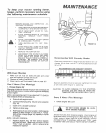
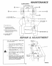
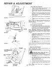
Side.to-Side mower Adjustment
a Depress lift lever plunger and use lift lever to raise
mower to maximum cutting height (Fig34)
b Measure height from bottom of curl to ground level at
front of mower_ Distance "A" should be the same (Fig.
34).
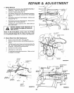
c ff distance ",4"needs to be changed, snap out access
hole cover on LH. side above footrest Use 11/16"
wrench on nuts "B" and "C" at side-to-side adjustment
trunnion (Fig. 35).
To raise left side of mower, loosen nut "B"and tighten nut
"C',
d
e
To lower left side of mower, loosen nut "C" and tighten
nut "B"
NOTE: ONE ROTATION OF ADJUSTMENT NUTS IS
EQUIVALENT TO APPROXIMATELY 5 MM (3/16")
HEIGHT CHANGE
f Be sure all nuts are securefy tightened
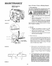
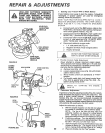
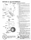
Front.To-Rear Mower Adjustment
a To obtain the best cutting results, your mower housing
should be adjusted so the front and rear flange distance
"[9" (Fig 36) is 13 mm (1/2") lower in front when the
mower is posihbned in the highest cutting position.
NOTE: MEASURE DISTANCE "D" FROM GROUND
LEVELTO BOTTOM OFCURL ON RIGHT REAR FLANGE
AND COMPARE TO DISTANCE "D" AT RIGHT FRONT
FLANGE
b To raise rear of mower, loosen nut "E" on both rear
suspension arms Screw both nuts "F" up an EQUAL
NUMBER OF TURNS (Fig 41)
c When distance "[3" is I3 mm (t/2") lower at front than
rear. tighten nuts "E"
d To lower rear of mower; loosen nut "F_ on both [e_t
suspension arms an EQUAL NUMBER OF TURNS (F i#
37).
e When distance "D" is I3 mm (1/2 "_)lower at front than
rear, retighten nuts "E"
NOTE: WHEN ADJUSTING REAR SUSPENSION TRUN-
NIONS ALWAYS ADJUST BOTH EQUALLY SO MOWER
WtLL STAY LEVEL
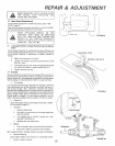
Mower Drive Belt Removal
NOTE: MOWER BELT INSTALLATION DECAL LO-
CATED ON MOWER HOUSING
REPLACE ONLY WITH THE BELTS
SPECIFIED IN THIS MANUAL.
............... i,,, i i ii i u
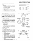
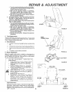
a Place attachment clutch switch in "Disengaged" posi.
tion (Fig. 38)
b Turn height adjustment knob to its lowest position.
Move attachment lift lever (Fig 38)forward to lower
mower to its lowest position
c. Rofl belt off engine pulley (Fig.. 39)
d. Pulfbeftoffboth mowerputley andidlerpulleys (Fig. 40)
e. To replace mower drive belt, reverse above proce-
dure
NOTE: MAKE SURE DRIVE BELT tS ENGAGED IN
ATTACHMENT 22 ALL PULLEYS,,
FIGURE 38 UFT LEVER