


ASSEMBLY
RETAINER
_ SPRING
/
MOWER
PARALLEL LINK
FIGURE 7
SUS.PE NSION
ARMS
HINGE
LiFT jLtFT
TRUNNION t BRACKET
FIGURE8
ATTACHMENT CLUTCH
SWITCH (C
PosmoN)
REAR HINGE
I_tN' LEVER
PLUNGER
HEIGHT ADJUSTMENT
KNOB
%
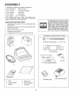
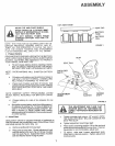
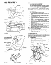
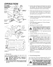
6. Mower and Drive Belt Installation
INSTALL MOWER PARALLEL LINK
Your tractor has been shipped with the mower parallel link
included in the parts carton, Install mower parallel link on
tractor (Fig. 7) using hinge pin and retainer spring,
NOTE: SMALLER END OF PARALLEL LINK MOUNTS
TO TRACTOR USE THE SHORTEST HINGE PIN FOR
MOUNTING,
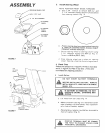
INSTALL MOWER
Your mower installs without the use of tools..
a, Raise attachement lift lever (Fig, 9) to its highest posi-
tion,.
b,, Turn height adjustment knob counterclockwise _ )
to lowest position (Fig, 10)
c, Slide mower under tractor with discharge guard to R,.H,
side
d Install rear hinge pin through mower flit brackets and
parallel link (Fig. 8), Secure with retainer spring,
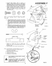
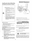
e Move attachment lift lever (Fig, 9) forward to lower
suspension arms, Remove retainer springs from fift
trunnions (Fig, 8)
f Slide trunnions through upper lift bracket holes and
secure with retainer springs (Fig 8),
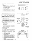
g, Pull L H idter putley (Fig_ 12) toward the right hand side
of the tractor and roll belt over engine pulley (Fig, 8)
NOTE: MOWER DRIVE BELT INSTALLATION DECAL
LOCATED ON MOWER HOUSING,
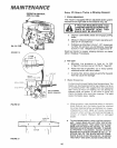
h. Use attachment lift lever (Fig 9) to raise mower,,
i Turn height adjustment knob clockwise ([_) to the
middle of its travel (Fig 10),
7o Check Cutting Level
The blade housing was set at the factory to cut tevet After mowing
a shortdistance, look atthe area that was cut, Iftheblade housing
cuts uneven, see "MOWER ADJUSTMENT," page 2I
8. Final Assembly
a Make sure all fasteners are tight.
b., Read and follow the operation instructions (page 1I),
Know the location and purpose of all controls,,
c, Check oil and gasoline (page I2) befGre staffing the
tractor,
L.H $OLER
NUT PULLEY
MOWER DRIVE
BELT
ATTACHMENT
UFT LEVER
SPR_NG
FIG URE 9
FIGURE 10
LOWER
HEIGHT ADJUSTMENT
KNOB
10
FIGURE 11
IDLER
PULLEY
i
'i
OWER L ;
PULLEY