


ASSEMBLY
Bend the ends of the cotter pin around the rod and
reinstall the plastic cap.
Tighten the eye bolt installed earlier, keeping eye in
line with the rod while tightening the inside securely
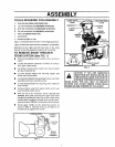
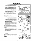
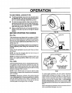
Rotate the chute crank fully clockwise and tullycounter-
clockwise. The discharge chule should
rotate fully to the outer diameter of the worm and
should clear approximately 1/8" (See FIG. 5). If the
chute crank needs to be adjusted, go to the
Service and Adjustments section in this manual•
Screws securing chute clips at the base of the chute
should be slightly loose for easy rotation
NOTE: Be sure the crank does not touch the side of the
engine or the cover will be scratched.
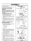
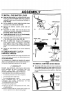
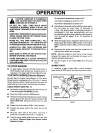
TO INSTALL HEADLIGHT
The headlight is mounted on the right side of the upper
handle. It is installed upside down for shipping purposes•
Remove the pivot bolt nut, lock washer and saddle
washer (FIG. 6A) from the headlight mounting bracket•
Remove headlight assembly and replace on top side
of upper handle with saddle washer, lock washer and
pivot bolt nut as shown in FIG. 6B Tighten nut
securely (See Headlight Repair Parts in the Repair
Parts section of this manual).
Tie the headlight cable to upper and lower handles
with the plastic cable ties supplied in theparts bag by
threading the pointed ends ot each tie through the
square end and pulling tightly around the headlight
cable and the handle.
NOTE: One side of the plastic tie has small notches in it,
while the other side is smooth. The notched side must be
on the inside of the loop which is formed when the ends are
put together,
• Try to loosen the cable tie. Ifit can be loosened, it has
been attached with the smooth side on the inside ol
the loop• Re move the cable tieand reverse its direction
• Cut off excess plastic tie.
TO ASSEMBLE CONTROL CABLES
PLASTIC\ . NOTCHEDSECTION
CAP COTTER _.
_1/8INCH CLEARANC
FLATWASHER 1
CRANK ADJUSTING ROD
WORM
1/2 INCH
FIG. 5
i
PtVOT;
BOLT
• C-= SADDLE
• ='_ASH ER
LOCK -
NASHER--_, CABLE
PIVOT--._ TIES
NUT
FIG. 6A FIG. 6B
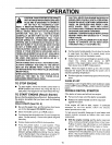
DRIVE
LEVER
• Install control cables tocontrol levers as shown in FIG.
7 and FIG. 7A.
NOTE: If control cables have become unattached from
motor mount frame, reconnect cables as shown _nFIG 7A
NOTE: Do not tangle headlight cable and clutch con-
trol cables.
FIG. 7
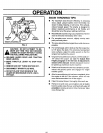
4" LG. FREE 3" LG. FREE
TRACTION STATE STATE
: / t iJ AUGER
DRIVE_ _/ _ _L__ /DRIVE
SPRING m,,_)_J_- _! :' A_""_ R PRING
4,,
DRIVE I: [_'Q"[J_, ,.¥ _;o\ I DRWE
SPRING _ I___I!I"_"--"_'_,T-S p RING
LEVER ""_ • _ LEVER
FIG. 7A
9