


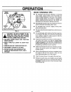
SERVICE AND ADJUSTMENTS
I
CAUTION: ALWAYS DISCONNECT THE I
SPARK PLUG WIRE AND TIE BACK
AWAY FROM THE PLUG BEFORE MAK-
ING ANY ADJUSTMENTS OR REPAIRS.
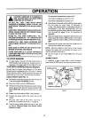
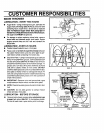
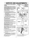
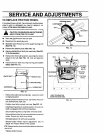
TO ADJUST SKID HEIGHT
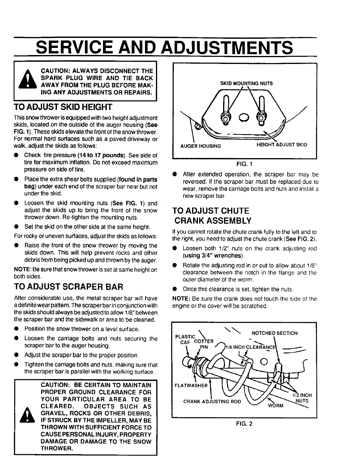
This snow thrower isequipped withtwo heightadjustment
skids, located on the outside of the auger housing (See
FIG. 1). These skidselevate the frontof the snowthrower.
For normal hard surfaces such as a paved driveway or
walk, adjust the skids as follows:
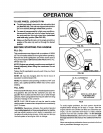
• Check tire pressure (14 to 17 pounds). See side of
tire for maximum inflation. Do not exceed maximum
pressure on side of tire.
• Place the extra shear boltssupplied (found in parts
bag) under each end ofthe scraper bar near but not
under the skid.
• Loosen the skid mounting nuts (See FIG. 1) and
adjust the skids up to bring the front of the snow
thrower down. Re-tighten the mounting nuts.
• Set the skid on the other side at the same height.
For rocky or uneven surfaces, adjustthe skids as follows:
• Raise the front of the snow thrower by moving the
skids down. This will help prevent rocks and other
debris from being picked up and thrown by the auger.
NOTE: Be sure that snow thrower is set atsame height on
both sides.
TO ADJUST SCRAPER BAR
After considerable use, the metal scraper bar will have
adefinite wear pattern. The scraper bar in conjunction with
the skids should always be adjusted to allow 1/8" between
the scraper bar and the sidewalk or area to be cleaned.
• Position the snow thrower on a level surface.
• Loosen the carriage bolts and nuts securing the
scraper bar to the auger housing.
Adjust the scraper bar to the proper position.
Tighten the carriage bolts and nuts, making sure that
the scraper bar is parallel with the working surface.
&
CAUTION: BE CERTAIN TO MAINTAIN
PROPER GROUND CLEARANCE FOR
YOUR PARTICULAR AREA TO BE
CLEARED. OBJECTS SUCH AS
GRAVEL, ROCKS OR OTHER DEBRIS,
IF STRUCK BY THE IMPELLER, MAY BE
THROWN WITH SUFFICIENT FORCE TO
CAUSE PERSONAL INJURY, PROPERTY
DAMAGE OR DAMAGE TO THE SNOW
THROWER.
SKID MOUNTING NUTS
O
AUGER HOUSING
HEIGHT ADJUST SKID
FIG. 1
After extended operation, the scraper bar may be
reversed. If the scraper bar must be replaced due to
wear, remove the carriage bolts and nuts and install a
new scraper bar.
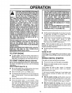
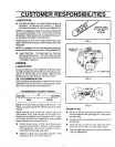
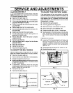
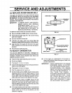
TO ADJUST CHUTE
CRANK ASSEMBLY
If you cannot rotate the chute crank fully to the left and to
the right, you need to adjust the chute crank (See FIG. 2).
• Loosen both 1/2" nuts on the crank adjusting rod
(using 3/4" wrenches).
• Rotate the adjusting rod in or out to allow about 1/8"
clearance between the notch in the flange and the
outer diameter of the worm.
• Once this clearance is set, tighten the nuts.
NOTE: Be sure the crank does not touch the side of the
engine or the cover will be scratched.
PLASTIC _ _ NOTCHED SECTION
OAF COTTER
I J
FLATWASHER
CRANK ADJUSTING ROD
WORM
1/2 INCH
FIG. 2