


,,=_............ i i=1 q ,u i,=,11=1 i iiii,
CAUTION: ALWAYS WEAR SAFETY
GLASSES OR EYE SHIELDS WHILE
ASSEMBLING EDGER.
ASSE BLY
ii , qlll, l,ii,i i ................... iii i , lil,i
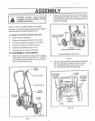
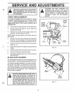
Attach the front wheel, with the ribs to the outside,
to the edger (See Fig 2) with a 3/8-16 x 1 390 inch
shoulder bolt and 3/8-16 hex wide flange lock nut
(found in parts bag),,
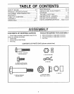
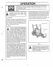
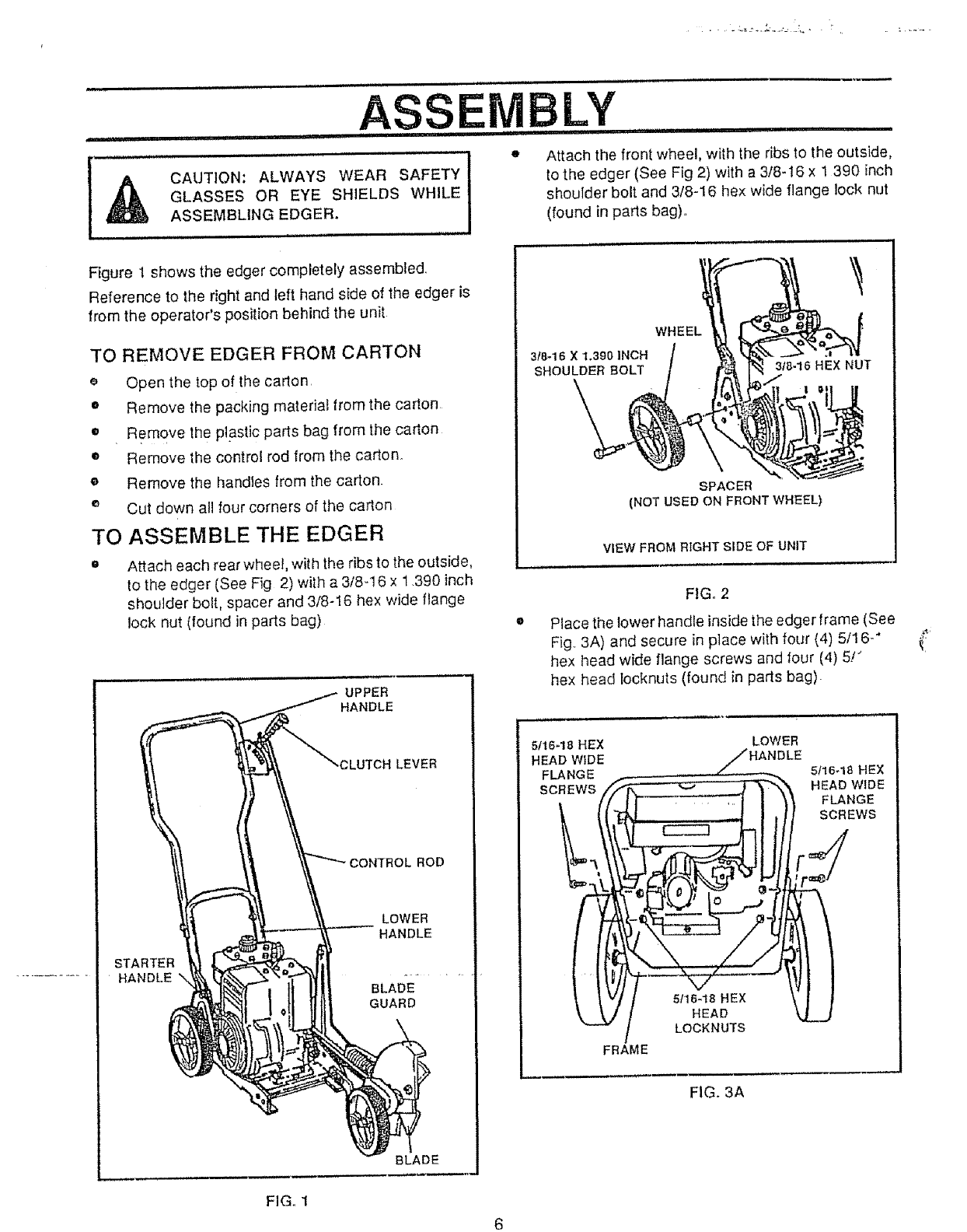
Figure 1 shows the edger completely assembled,
Reference to the right and left hand side of the edger is
from the operator's position behind the unit
TO REMOVE EDGER FROM CARTON
_' Open the top of the carton
• Remove the packing material from the cation
= Remove the plastic parts bag from the carton
• Remove the control rod from the carton.
• Remove the handles from the carton.
e Cut down all four corners of the carton
TO ASSEMBLE THE EDGER
= Attach each rear wheel, with the ribs to the outside,
to the edger (See Fig 2) with a 3/8-16 x 1,390 inch
shoulder bolt, spacer and 3/8-16 hex wide flange
lock nut (found in parts bag)
UPPER
HANDLE
CLUTCH LEVER
STARTER
HANDLE
LOWER
HANDLE
BLADE
GUARD
BLADE
3tS-16X1o390]NCH
SHOULDER BOLT
WHEEL
318.16 HEX NUT
SPACER
(NOT USED ON FRONT WHEEL)
VIEW FROM RIGHT SIDE OF UNIT
FIG. 2
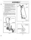
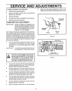
Place the lower handle insidethe edger frame (See
Fig. 3A) and secure in place with four (4) 5/16-"
hex head wide flange screws and four (4) 5/_
hex head bcknuts (found in parts bag).
5t16-18 HEX LOW ER
HEAD WIDE /HANDLE
FLANGE _ 5t16-18 HEX
SCREWS
i
FRAME
FIG. 3A
FIG_ 1