


6
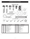
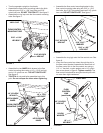
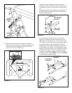
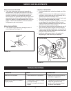
FIGURE 2
FIGURE 3
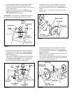
• Turn the spreader upside down as shown in gure 1.
• Remove the lock nut from the middle bolt in the
crossover tube and shaft support plate. Leave the bolt
in place. See gure 1.
• Assemble the hitch tube onto the middle bolt and
secure it with the same lock nut you removed. DO
NOT TIGHTEN YET. See gure 1.
IMPORTANT: The hitch tube must attach to the side of
the crossover tube opposite the shaft support plate.
1/4" x 1-3/4"
HEX BOLT
1/4" NYLOCK
HEX NUT
HITCH BRACE
OUTER
HITCH
TUBE
HITCH BRACE
OUTER
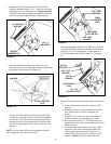
• Assemble a spacer, a 3/4" at washer, a wheel (air
valve facing out) and another 3/4" at washer onto
the end of the axle that has only the small hole. See
gure 3.
• Install a 1/8" x 1-1/2" cotter pin into hole in the axle.
See gure 3.
SMALL HOLE
SPACER
3/4" DIA.
FLAT WASHER
1/8" x 1-1/2"
COTTER PIN
AIR VALVE
FIGURE 4
• Assemble a spacer, a 3/4" at washer, a wheel (air
valve facing out) and another 3/4" at washer onto
the end of the axle that has both the large and small
holes. See gure 4.
• Install a 1/8" x 3/4" cotter pin into the small hole in the
end of the axle. See gure 4.
• Open the bail on the drive pin and install it through the
wheel and the large hole in the axle. Close the bail to
lock the pin in place. See gure 4.
DRIVE PIN
AIR VALVE
SPACER
3/4" DIA.
FLAT WASHER
1/8" x 1-1/2"
COTTER PIN
CROSSOVER
TUBE
HITCH
TUBE
SHAFT
SUPPORT
PLATE
MIDDLE
LOCK NUT
MIDDLE BOLT
FIGURE 1
• Assemble two hitch braces per side to the inside of
the hopper frame using a 1/4" x 1-3/4" hex bolt and
1/4" hex lock nut on each side. DO NOT TIGHTEN
YET. See gure 2.
• Assemble the OUTER hitch braces to the hitch tube
using a 1/4" x 1-3/4" hex bolt and a 1/4" nylock hex
nut. DO NOT TIGHTEN YET. Do not assemble the
inner hitch braces at this time. See gure 2.