


7
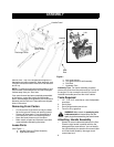
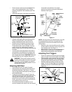
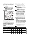
• Secure bottom hole in the handle to the snow
thrower using 5/16 x0.75" hex bolt and lock
washer from the hardware pack (group A on
page5 ).
Do not tighten at this time. See Figure 2.
Figure 2
• Place a handle tab, included in the hardware
pack (group A on page5), over the upper hole in
handle so that the contour of the handle tab
matches that of the handle. See Figure 2.
• Secure handle tab to the snow thrower using
hex bolt (5/16 x 1.75" long) and lock washer
from the same group in the hardware pack. Do
not tighten at this time.
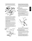
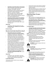
• Attach the left handle in the same manner. Do
not tighten at this time.
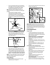
• Place the handle panel in position between the
handles so the ends of the curved part of the
handles go through the slots in the handle panel.
While placing the handle panel, make sure to
route chute and chute cable between the
handles underneath the panel keeping the cable
on top of the engine. Align the holes in the
handle with the holes on two sides of the handle
panel. See Figure 3.
Figure 3
Handle
Tab
Hex Bolt (3/4”)
Lock Washer &
Hex Bolt (1-3/4”)
Lock Washer &
Right Handle
Right Handle
Hex Bolt
and Flange
Nut
Carriage Bolt,
Cupped Washer
and Hex Nut
Handle Panel
Align Holes
• Attach the handle panel to the handle with two
carriage bolts, cupped washers (cupped side
against the handle panel) and hex nuts on each
side. See Figure 3. You will find these fasteners
in the hardware pack (group B on page5). Align
the contour of the carriage bolt head with the
handle.
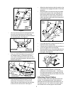
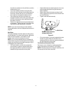
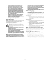
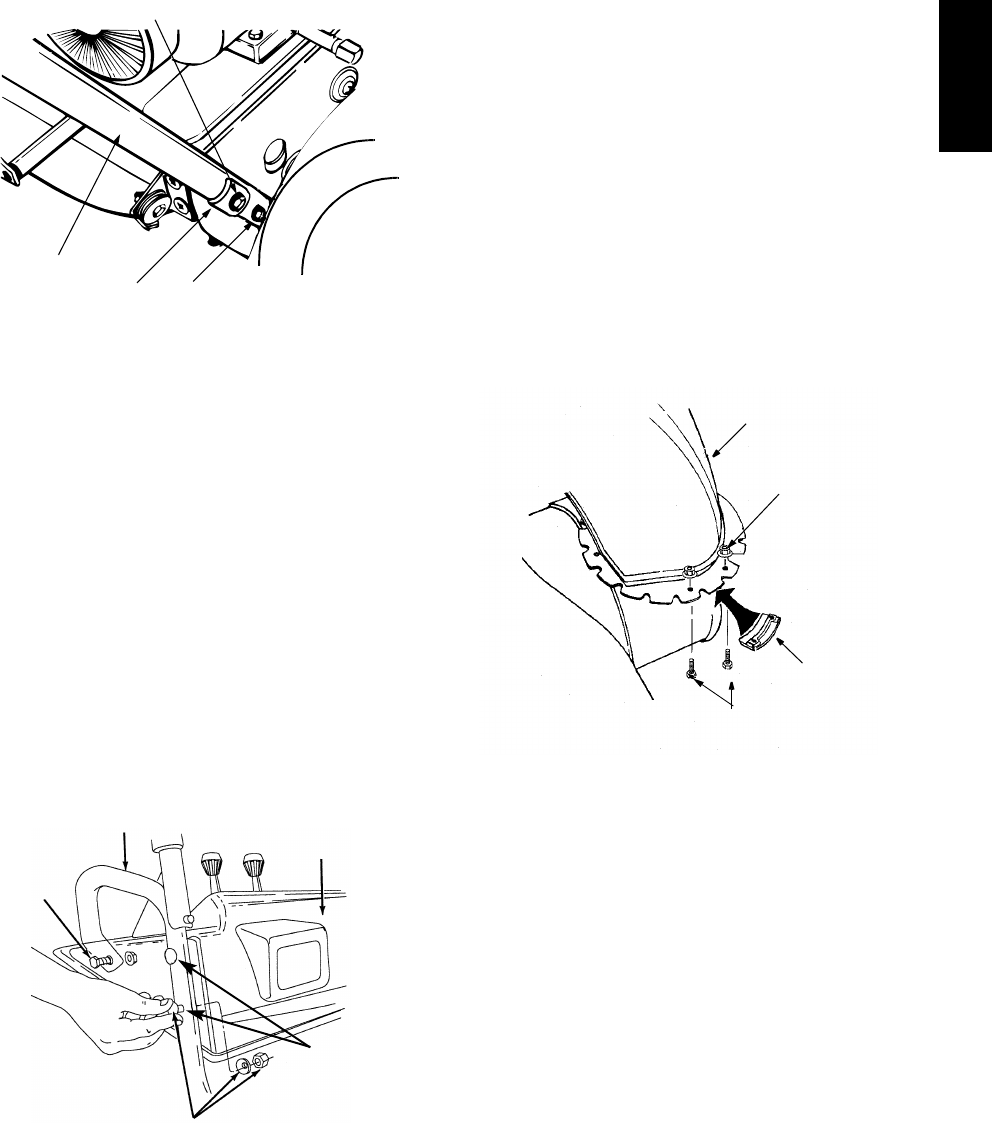
Attaching Chute
• Place the chute assembly over the chute
opening with the chute facing front of the unit.
NOTE: Make sure that the chute cables are
straightened while assembling the chute.
• Place the chute flange keeper (flat side down)
beneath lip of chute assembly as shown in
Figure 4.You will find the chute flange keepers in
group E of the hardware pack.
• Insert 1/4-20 hex bolt and flange nut from group
E up through chute flange keeper and chute
assembly as shown in Figure 4. Do not tighten at
this time. Rotate chute to install all the flange
keepers.
Figure 4
• After assembling all three chute flange keepers,
tighten, then back off 1/4 turn to allow easier
movement of the chute. Use (2) 7/16" wrenches.
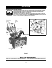
Attaching Chute Crank
• On the left side of the handle panel, place the
upper chute crank bracket on to the inside of the
handle panel support. See Figure 5. You will find
this bracket and associated hardware in group F
of hardware pack.
• Insert hex bolt through the upper chute crank
bracket, handle panel support, and upper left
handle. Secure the bracket using cupped
washer and hex nut. Make sure that the cupped
side of the washer is set against the handle.
Chute
Hex
Nut
Chute
Flange
Keeper
Flange
Hex
Bolt
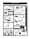
ASSEMBLY