


48 Cheetah 10K.7 SCSI Product Manual, Rev. D
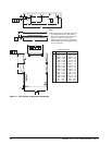
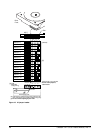
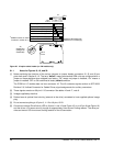
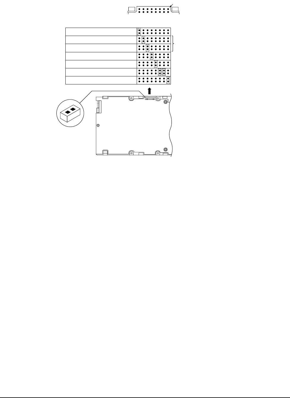
Figure 20. J2 option select header (on LW models only)
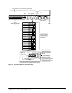
8.1.1 Notes for Figures 18, 19, and 20.
[1] Notes explaining the functions of the various jumpers on jumper header connectors J2, J5, and J6 are
given here and in Section 8.1.2. The term “default” means as standard OEM units are configured with a
jumper on those positions when shipped from factory. “Off” means no jumper is installed; “On” means a
jumper is installed. OFF or ON underlined is factory default condition.
The PCBA on LC models does not have connector J5. The J5 connector signals conform to SFF-8009
Revision 2.0, Unitized Connector for Cabled Drives, signal assignments for auxiliary connectors.
[2] These signals are also on 80-pin J1 I/O connector. See tables 16 and 17, note 9.
[3] Voltage supplied by the drive.
[4] Dashed area is optional host circuitry (external to the drive) connected to host supplied optional usage
plug.
[5] Do not connect anything to J5 pins 9, 11-12 or J6 pins 13-20.
[6] Connect an external Drive Activity LED to J6 pins 11 and 12 (see Figure 18), or to J5 pin 8 (see Figure 19)
and the drives +5V power source, through an appropriately sized current limiting resistor. The drive pro-
vides an internal 150 ohm current limiting resistor for the J6 connection.
Delay Motor Start
Enable Remote Motor Start
Write Protect
Parity Disable
Term. Power to SCSI Bus
S
E
D
S
M
E
W
P
P
D
R
E
S
R
E
S
T
P
Jumper
Positions
Force single-ended bus mode
(applies to LW models only;
reserved on LC models)
Pin 1
Reserved
J2
J2
Jumper Plug
(enlarged to
show detail)
[3]
*Additional notes on these
functions in section 8.1.2.
J2
Drive
Front
J6
[2]