


7
WARNING:
If any parts are damaged or missing, do not operate
this tool until the parts are replaced. Failure to heed this
warning could result in serious personal injury.
WARNING:
Do not attempt to modify this tool or create accesso-
ries not recommended for use with this tool. Any such
alteration or modification is misuse and could result in a
hazardous condition leading to possible serious personal
injury.
WARNING:
Do not connect to power head until assembly is complete.
Failure to comply could result in accidental starting and
possible serious personal injury.
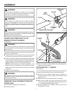
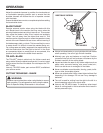
JOINING THE POWER HEAD TO THE
BRUSHCUTTER ATTACHMENT
See Figure 2.
WARNING:
Never attach or adjust any attachment while power head
is running. Failure to stop the engine may cause serious
personal injury.
The brushcutter attachment connects to the power head by
means of a coupler device.
Loosen the knob on the coupler of the power head shaft
and remove the end cap from the attachment shaft.
Push in the button located on the attachment shaft. Align
the button with the guide recess on the power head cou-
pler and slide the two shafts together. Rotate attachment
shaft until button locks into the positioning hole.
NOTE: If the button does not release completely in the
positioning hole, the shafts are not locked into place.
Slightly rotate from side to side until the button is locked
into place.
Tighten the knob securely.
WARNING:
Be certain the knob is fully tightened before operating
equipment. Check it periodically for tightness during use
to avoid serious injury.
REMOVING THE ATTACHMENT FROM THE
POWER HEAD
For removing or changing the attachment:
Loosen the knob.
Push in the button while twisting and pulling apart the
upper and lower sections.
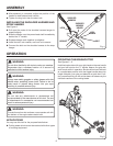
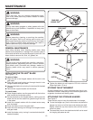
ATTACHING THE “J” HANDLE
See Figure 3.
The “J” handle must be used to ensure the best control and
maximize operator safety when using the brushcutter.
Hold the top and bottom clamp snugly in position on
the shaft housing so that handle will be located to the
operator’s left.
Insert the end of the handle between the clamps.
Align the bolt holes and push the long bolt (1/4-20 x
1-1/2 in.) through the handle side. Place short bolt (1/4-20
x 1 in.) through opposite side of clamp.
Install flat washers, lock washers, and hex nuts to hold
the assembly in place.
ASSEMBLY
Fig. 2
KNOB
COUPLER
BRUSHCUTTER ATTACHMENT
POWER HEAD
SHAFT
POSITIONING
HOLE
GUIDE
RECESS
BUTTON
Fig. 3
CLAMP
FLAT WASHER
LOCK WASHER
HEX NUT
J-HANDLE
BOLTS