


10
WARNING:
When servicing, use only identical replacement parts.
Use of any other parts may create a hazard or cause
product damage.
WARNING:
Always wear safety goggles or safety glasses with side
shields during tool operation. If operation is dusty, also
wear a dust mask.
WARNING:
Before inspecting, cleaning, or servicing the machine,
shut off engine, wait for all moving parts to stop, and
disconnect spark plug wire and move it away from spark
plug. Failure to follow these instructions can result in
serious personal injury or property damage.
GENERAL MAINTENANCE
Avoid using solvents when cleaning plastic parts. Most
plastics are susceptible to damage from various types of
commercial solvents and may be damaged by their use. Use
clean cloths to remove dirt, dust, oil, grease, etc.
WARNING:
Do not at any time let brake fluids, gasoline, petroleum-
based products, penetrating oils, etc., come in contact
with plastic parts. Chemicals can damage, weaken or
destroy plastic which may result in serious personal
injury.
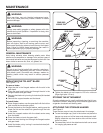
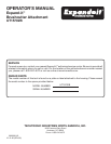
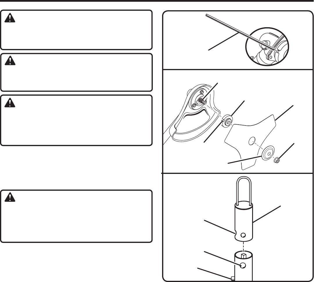
REPLACING THE TRI-ARC
®
BLADE
See Figures 7 - 8.
To remove blade:
Align the slot in the flanged washer with the slot in the
gear head.
Place the gear head locking tool through the slot in the
flanged washer and gear head.
Remove the blade nut by turning it clockwise (left-handed
threads)
.
Remove the cupped washer and the blade.
To install blade:
� Place flanged washer over the gear shaft with the hollow
side toward the brushcutter guard.
� Center the blade on the flanged washer, making sure the
blade fits flat and the raised hub goes through the hole
in the blade.
�� Install the cupped washer with the raised center away
from the blade.
�� Place the blade nut onto the gear shaft.
Insert the head locking tool through the flanged washer
and gear head.
�� Install the blade nut by turning it counterclockwise (left-
handed threads).
MAINTENANCE
Fig. 8
Fig. 9
BUTTON
HOLE
HANGER
CAP
SECONDARY
HOLE
Fig. 7
GEAR HEAD
LOCKING TOOL
BLADE NUT
CUPPED
WASHER
SLOT
FLANGED
WASHER
BLADE
GEAR SHAFT
�� Tighten the blade nut and torque to 120 in.lb. minimum
(finger tight plus 1/2 turn).
STORING THE ATTACHMENT
Store the attachment in a well-ventilated place that is inac-
cessible to children. Keep away from corrosive agents such
as garden chemicals and deicing salts.
ATTACHING THE STORAGE HANGER
See Figure 9.
There are two ways to hang the attachment for storage.
To use the hanger cap, push in the button and place the
hanger cap over end of the lower end attachment shaft.
Slightly rotate the cap from side to side until the button
locks into place.
The secondary hole in the attachment shaft can be used
for hanging purposes as well.