


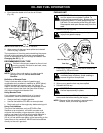
OIL AND FUEL INFORMATION
ASSEMBLY INSTRUCTIONS
12
RECOMMENDED OIL TYPE
Using the proper type and weight of oil in the
crankcase is extremely important. Check the
oil before each use and change the oil
regularly. Failure to use the correct oil, or
using dirty oil, can cause premature engine wear and
failure.
Use a high-quality SAE 30 weight oil of API (American
Petroleum Institute) service class SF, SG, SH.
ADDING OIL TO CRANKCASE – INITIAL USE
NOTE: This unit is shipped without being filled with oil.
In order to avoid damage to the unit, put oil in
the crankcase before attempting to start unit.
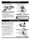
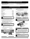
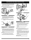
Your unit is supplied with one 3.4 fluid oz. (100 ml.)
bottle of SAE 30 SF, SG, SH oil (Fig. 17).
NOTE: Save the bottle to measure the correct amount
for future oil changes. See Changing the Oil
Pg. 20.
1. Unscrew the top of the bottle of oil and remove the
paper seal covering the opening. Replace top. Cut
the tip off the funnel spout (Fig. 17).
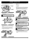
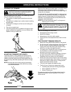
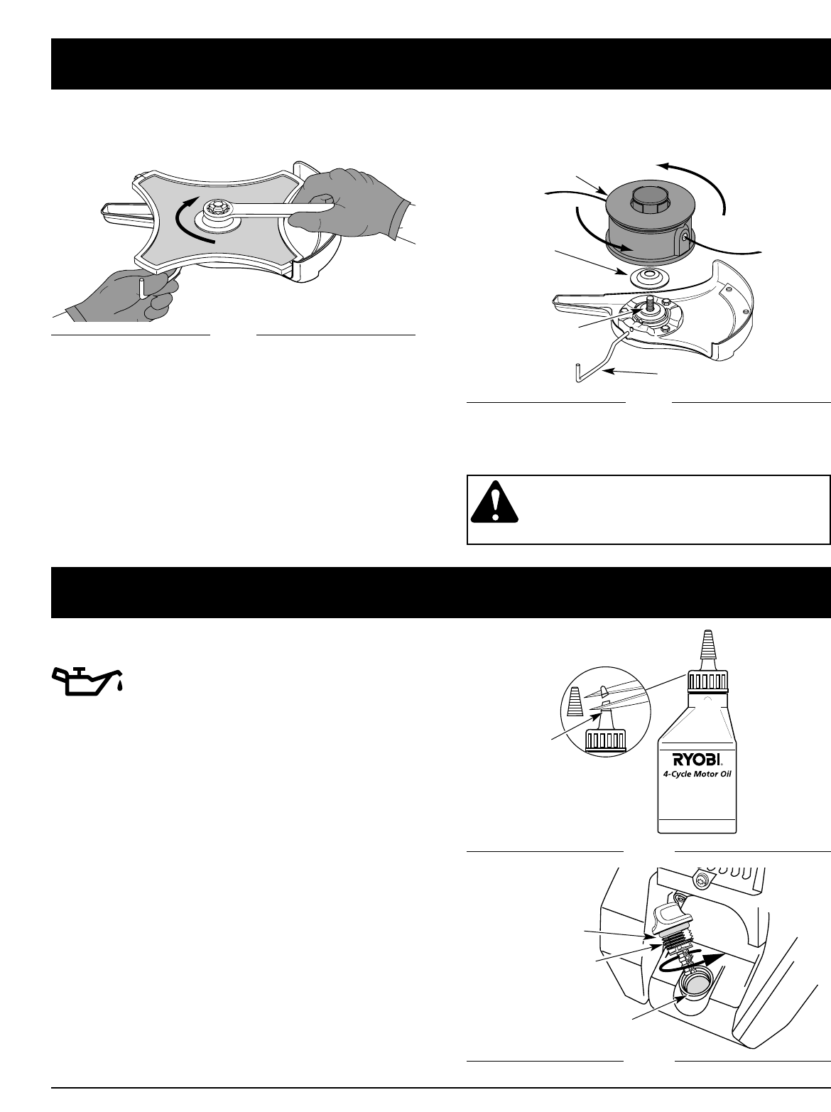
2. Place the unit on a flat level surface.
3. Remove the oil plug / dipstick from the crankcase
(Fig. 18).
Fig. 17
Oil Fill Plug/Dipstick
Oil Fill Hole
Fig. 18
O-Ring
Funnel Spout
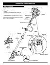
Cutting Attachment
Locking Rod
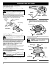
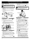
4. Remove the nut, blade retainer, and blade. Store the
nut and blade together for future use in a secure
place. Store out of reach of children.
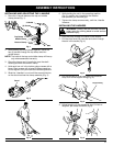
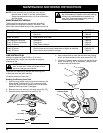
Install the Cutting Attachment
5. Align the shaft bushing hole with the locking rod slot
and insert the locking rod into the shaft bushing hole.
(Fig. 8, Pg. 10). Place the blade retainer on the
output shaft with the flat surface against the output
shaft bushing as shown in Fig. 16. Screw the cutting
attachment counterclockwise onto the output shaft.
Tighten securely.
Clockwise
6. Remove the locking rod.
7. Install the cutting attachment shield. See Removing
and Installing Cutting Attachment Shield, Pg. 10.
WARNING: To avoid serious personal injury,
the cutting attachment shield SHALL be in
place at all times while operating the unit as
a grass trimmer.
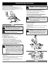
3. While holding the locking rod, loosen the nut on
the blade by turning it clockwise with a 5/8 inch
closed-end or socket wrench (Fig. 15).
NOTE: The blade retainer must be installed on the
output shaft in the position shown for the cutting
attachment to work correctly.
Blade Retainer
Output Shaft
Bushing
Fig. 15
Fig. 16