


ASSEMBLY INSTRUCTIONS
11
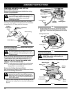
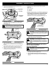
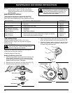
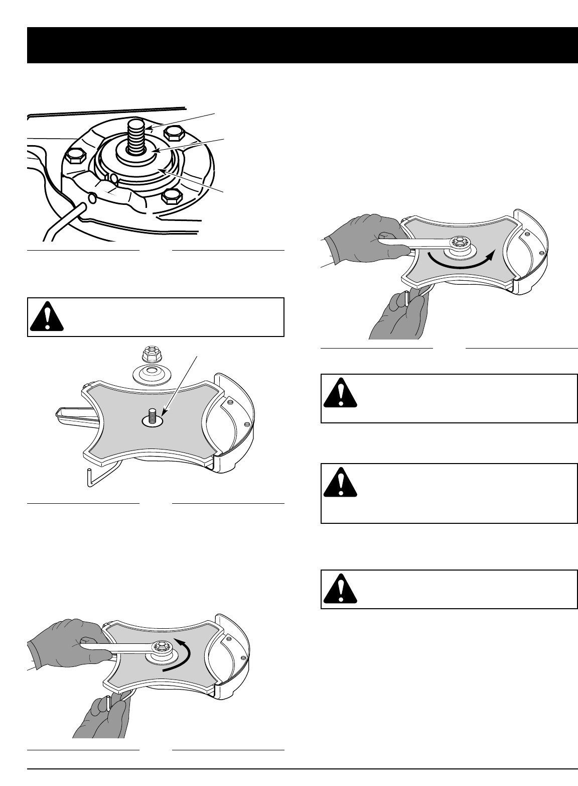
4. Center the cutting blade on the pilot step of the
output shaft bushing (Fig. 11).
Pilot Step
Output Shaft
Bushing
Output Shaft
Fig. 12
Fig. 13
Fig. 14
Fig. 11
5. Make sure that the cutting blade is centered on the
pilot step and sitting flat against the output shaft
bushing (Fig. 12).
WARNING: If the cutting blade is off-center,
the unit will vibrate, and the blade may fly off,
which can cause serious personal injury.
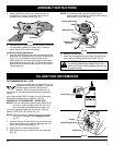
6. Align the shaft bushing hole with the locking rod
slot and insert the locking rod into the bushing hole
(Fig. 8).
7. Put the blade retainer and nut on the output shaft.
Make sure that the blade is installed correctly.
8. Tighten counterclockwise against the blade while
holding the locking rod (Fig. 13).
Counterclockwise
Pilot Step
9. Remove the locking rod from the locking rod slot.
WARNING: To avoid serious personal injury
or damage to the unit, do not start or operate
this unit with the locking rod in the locking
rod slot.
10. Remove the cutting blade cover by un-snapping the
plastic lock on the cover and pulling it from the
blade. Store the cover for future use.
WARNING: Do not sharpen the cutting
blade. Sharpening the blade can cause the
blade tip to break off while in use. This can
result in severe personal injury. Replace the
blade.
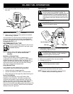
REMOVE THE CUTTING BLADE AND INSTALL
THE CUTTING ATTACHMENT
Remove the Cutting Blade
WARNING: To avoid serious personal injury,
always wear gloves while handling or
installing the blade.
1. Install the cutting blade cover. Pull the cover around
the blade and click the plastic lock.
2. Align the shaft bushing hole with the locking rod
slot and insert the locking rod into the bushing hole
(Fig. 8).
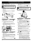
1/4-1/2 turn
Counterclockwise
• If using a torque wrench and an 5/8 inch socket
tighten to;
325 - 335 in•lb,
27 - 28 ft.•lb,
37 -38 N•m.
• Without a torque wrench, use a 5/8 inch closed-end or
socket wrench, turning the nut until the blade retainer
is snug against the shaft bushing. Make sure that the
blade is installed correctly, then rotate the nut an
additional 1/4 to 1/2 turn counterclockwise (Fig. 14).