


ASSEMBLY INSTRUCTIONS
10
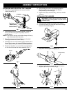
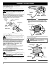
Install the cutting attachment shield when using the
unit as a grass trimmer.
WARNING: To avoid serious personal injury,
the cutting attachment shield SHALL be in
place at all times while operating the unit as
a grass trimmer.
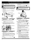
Install the cutting attachment shield on the shield mount
by inserting the three (3) screws into the shield mount.
Tighten securely with a flat blade screwdriver (Fig. 7).
REMOVE THE CUTTING ATTACHMENT AND
INSTALL THE CUTTING BLADE
NOTE: To make removing or installing the cutting blade
or cutting attachment easier, place the unit on
the ground or on a work bench.
Remove the Cutting Attachment Shield
See Removing and Installing Cutting Attachment Shield,.
Remove the Cutting Attachment
WARNING: The gear housing gets hot with
use and can result in injury to the operator.
When the unit is turned off it remains hot for
a short time. Do not touch the gear housing
until it has cooled.
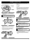
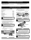
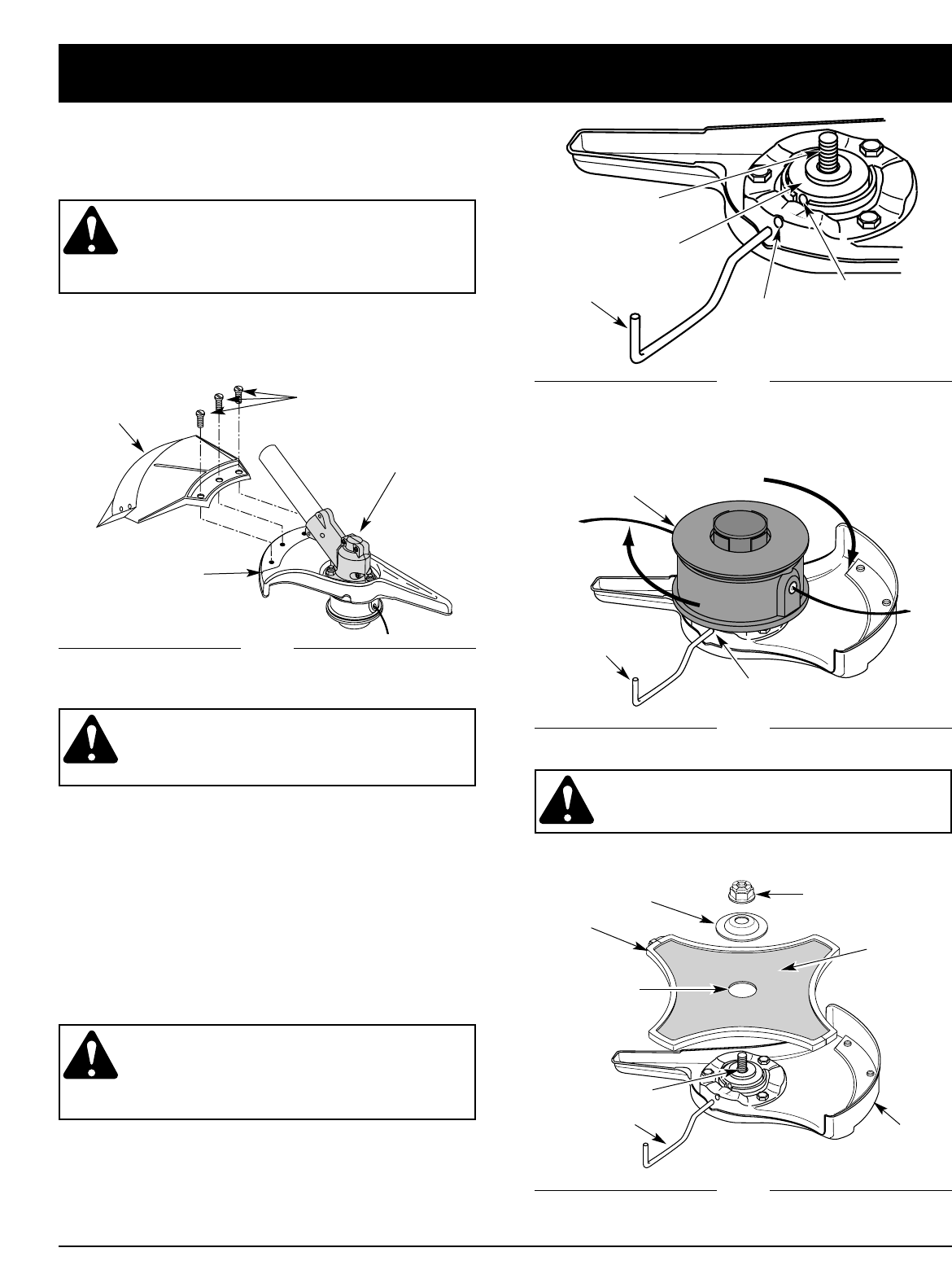
1. Align the shaft bushing hole with the locking rod slot
and insert the locking rod into the shaft bushing hole
(Fig. 8).
REMOVING AND INSTALLING CUTTING
ATTACHMENT SHIELD
Remove the cutting attachment shield when using
the unit as a brushcutter.
WARNING: The cutting attachment shield
should NOT be installed when operating the
unit with a blade. Remove the cutting
attachment shield before removing or
installing the blade.
Remove the cutting attachment shield from the shield
mount by removing the three (3) screws with a flat blade
screwdriver (Fig. 7). Store parts for future use.
(3) Screws
Cutting
Attachment
Shield
Shield Mount
Gear Housing
Shield
Mount
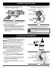
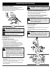
Install the Cutting Blade
WARNING: To avoid serious personal injury,
always wear gloves while handling or
installing the blade.
3. Place the cutting blade on the output shaft (Fig. 10).
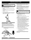
Cutting Attachment
Locking Rod
Cutting
Blade
Blade Retainer
Nut
Locking Rod Slot
Blade Cover
Locking Rod
Output Shaft
Pilot Hole
Shaft
Bushing Hole
Locking
Rod Slot
Output Shaft
Bushing
Locking Rod
Output Shaft
2. While holding the locking rod, remove the cutting
attachment by turning it clockwise off of the output
shaft (Fig. 9). Store the cutting attachment for future
use.
Fig. 7
Fig. 8
Fig. 9
Fig. 10