


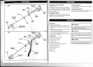
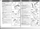
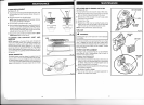
INSTALLING
THE
POWER
HEAD TO THE
ATTACHMENT
See
Figure
2.
A
wRnulruc'
Never
install,
remove,
or adjust
any attachment while
power
head
is running.
Failure
to
stop the engine can
cause
serious
personal
injury.
The
attachment
connects
to the
power
head bv means of
a
coupler
device.
r
Loosen
the knob on
the
coupler
of the
power
head
shaft
and
remove
the end cap
from the attachment.
r
Push
in
the button
located
on the
attachment
shaft. Align
the buttonwith
theguide
recessonthe
powerhead
coupler
and
slide
the two shafts together.
Rotate
the attachment
shaft
until
the button locks into the
positioning
hole.
NOTE:
lf
the button does not release completely in
the
positioning
hole, the shafts are not locked into
place.
Slightly
rotate from side to side uniil the button
is locked
into
place.
r
Tighten the knob securely.
A wlnuuc,
Be cedain the knob is fully
tightened before operating
equipment; check
it
periodically
for
tightness during use
to
avoid serious
personal
injury.
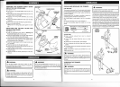
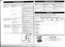
REMOVING
THE ATTACHMENT
FROM THE
POWER HEAD
For removing or changing
the attachment:
I
Loosen the knob.
I
Push in the button and twist
the shafts to
remove and
seoarate ends.
ATTACHING THE STORAGE
HANGER
See Figure 3.
There are two ways to
hang
your
attachment
for storage.
I
To use the hanger cap,
push
in the
button
and
place
the
hanger cap over end of
the lower end attachment
shaft.
Slightly
rotate the cap from side to side until
the button
locks
into
olace.
I
The secondary
hole in the attachment shaft can
be used
for
hanging
purposes
as well.
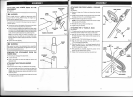
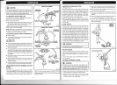
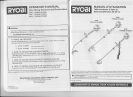
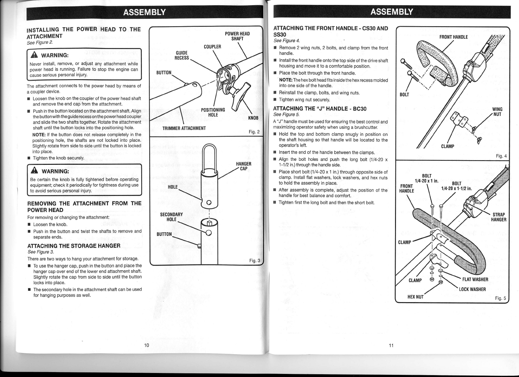
ATTACHING
THE FRONT
HANDLE
-
CS3O AND
SS3O
See
Figure
4.
I
Remove
2 wing nuts, 2 bolts,
and clamp from the
front
handle.
r
Install
the front handle onto the
too side of the
drive shaft
housing
and move it to
a comfortable
position.
I
Place
the
bolt
through
the front handle.
NOTE:The
hex bolt head fits insidethe
hex recess
molded
into
one side of the handle.
r
Reinstall
the clamp,
bolts, and wing
nuts.
r
Tighten
wing nut
securely.
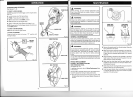
ATTACHING THE
UJ"
HANDLE
-
BC3O
See
Figure
5.
A
"J"
handle must
be used for ensuring the
best control
and
maximizing operator
safety when using
a brushcutter.
I
Hold the top
and bottom clamp
snugly in
position
on
the
shaft housing
so
that
handle will
be
located
to the
ooerator's
left.
r
lnsen
the end ofthe handle
between the
clamps.
I
Align the bolt holes
and
push
the
long bolt
(1/4-20
x
1-112
in.) through the handle
side.
r
Place
short boll(1/4-20
x 1 in.) through
opposite side
of
clamp.
Inslall flat washers,
lock washers,
and hex nuts
to hold the
assembly in
place.
I
After
assembly is complete,
adjust the
position
of the
handle for
best balance and
comfort.
I
Tighten first
the long bolt
and
then
the short bolt.
r^
i
"'
B0LT
\
1/4-20 x1-1l2in.
)/x
10