


24
MAINTENANCE AND REPAIR INSTRUCTIONS (Continued)
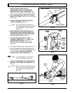
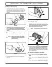
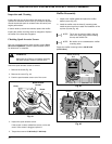
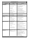
3. Remove the rocker arm cover and gasket, using a T-
25 Torx
®
screwdriver (Fig. 50).
Fig. 50
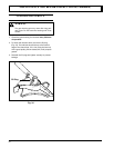
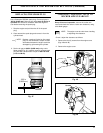
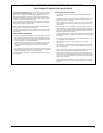
Flat Feeler Gauge
Valve
Rocker Arm
Fig. 51
4. Position the crankshaft so the piston is at the top of
the compression stroke (the rocker arms are free and
loose).
5. Measure the clearance between the valve stems and
rocker arms, using a
flat feeler gauge (Fig. 51).
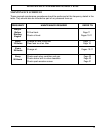
The recommended valve to rocker arm clearance for both
the intake and exhaust is
003-.006 in. (.076 mm-.152
mm).
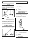
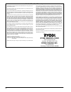
6. If the clearance is not within specification, adjust as
follows:
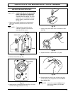
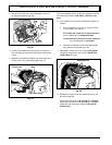
a. Turn the adjusting nut (Fig. 52), using an 5/16 in
(8 mm) wrench or nut driver.
To increase the rocker arm to valve clearance,
turn the adjusting nut counterclockwise.
To decrease the rocker arm to valve clearance,
turn the adjusting nut clockwise.
b. Recheck the clearance with a flat feeler gauge
and readjust as necessary (Fig. 49).
7. Reinstall the rocker arm cover using a new gasket.
Torque the rocker arm cover screw to 20-30 in•lb
(2.2-3.4 N•m)
(Fig. 50).
Fig. 52
Adjusting Nuts
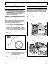
8. Reinstall the engine cover and screws (see Figs. 48
and 49 on page 22).
Torque the top screws to
10-12 in•lb (1.1-1.3 N•m).
Torque the front screw to 10-15 in•lb (1.1-1.7 N•m).
Torque the rear screw with washer to 25-30 in•lb
(2.8-3.4 N•m).