


MAINTENANCE AND REPAIR INSTRUCTIONS
12
11. Install the bump head cover over the inner reel. Align
the tabs on the cover with the slots in the outer
spool and press the cover evenly down until it snaps
into place .
NOTE: Make sure the bump head cover tabs snap into
place or the inner reel will come out during
operation.
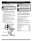
8. Insert the end of the line through the eyelet in the
outer spool (Fig. 15)
INSTALLING A PREWOUND REEL
Always use genuine replacement line. Using larger line
then the unit is designed for may make the motor
overheat or fail.
1. Remove the bump head cover by pressing in both
bump head cover tabs visible on either side of the
bump head outer spool (Fig. 11, Pg. 11).
NOTE: The spring will push the cover up when the tabs
release.
2. Remove the old inner reel and spring from the outer
spool (Fig. 11, Pg. 11).
3. Remove the spring from the old inner reel
(Fig. 11, Pg. 11).
4. Use a clean cloth to clean the inner surface of the
outer spool (Fig. 11, Pg. 11).
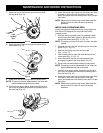
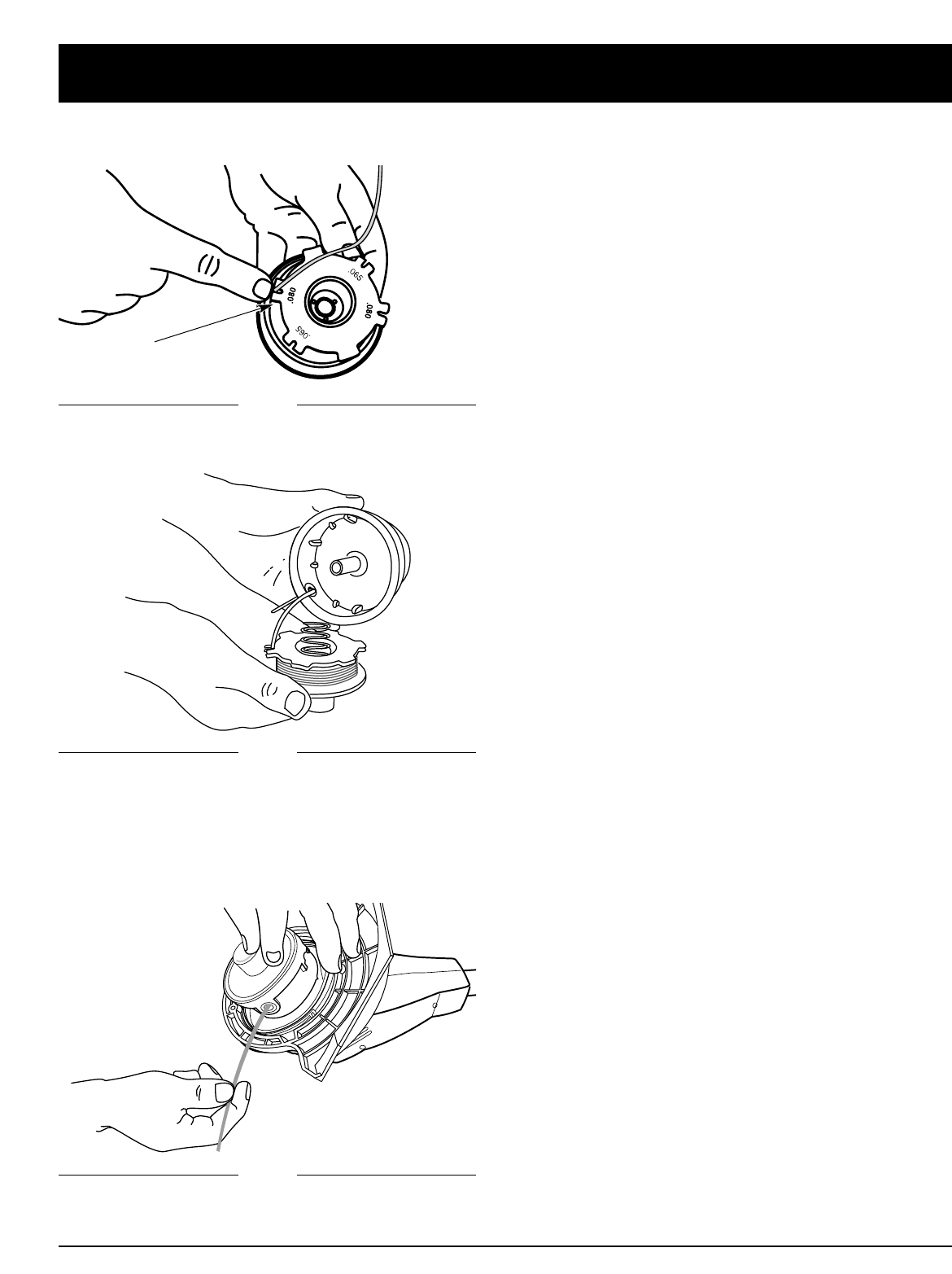
5. Insert the end of the line, on the prewound reel,
through the eyelet in the outer spool (Fig. 15)
6. Place inner reel and spring inside the outer spool.
NOTE: The spring must be assembled on the inner reel
before reassembling the bump head.
7. Hold the inner reel in place, grasp the line end and
pull firmly to release the line from the holding slot in
the inner reel (Fig. 16).
8. Install the bump head cover over the inner reel. Align
the tabs on the cover with the slots in the outer
spool and press the cover evenly down until it snaps
into place.
NOTE: Make sure the bump head cover tabs snap into
place or the inner reel will come out during
operation.
9. Place inner reel and spring inside the outer spool.
NOTE: The spring must be assembled on the inner reel
before reassembling the bump head.
10. Hold the inner reel in place, grasp the line end and
pull firmly to release the line from the holding slot in
the inner reel (Fig. 16).
Fig. 15
Fig. 16
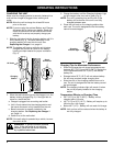
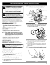
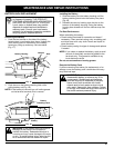
7. Insert the end of the line into one of the two 0.80
holding slots (Fig. 14).
Fig. 14
0.80
Holding
Slot