11
Controls
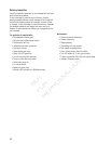
Generator
Read this Operator’s Manual and Important Safety Instructions before operating your generator.
Compare the illustrations with your generator to familiarize yourself with the locations of various controls and
adjustments. Save this manual for future reference.
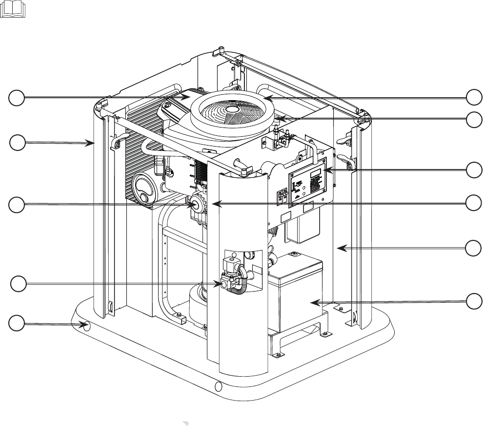
Generator is shown with roof and access covers removed for
clarity.
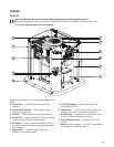
A - Lifting Holes — Provided at each corner for lifting
generator.
B - Fuel Inlet/Fuel Solenoid — Attach appropriate fuel
supply to generator here.
C - Oil Filter — Filters engine oil to prolong generator life.
D - Exhaust Port — High-performance muffler lowers engine
noise to comply with most residential codes.
E - Air Cleaner — Uses a dry type filter element and foam
pre-cleaner to protect engine by filtering dust and debris
out of intake air.
F - Engine Label — Located on engine valve cover.
Identifies engine model and type.
G - Oil Fill Cap/Dipstick — Check and fill engine with
recommended oil here.
H -
Control Panel — Used for various test, operation and
maintenance functions. See System Control Panel.
J -
Oil Drain Hose — Located inside access panel, next to
oil filter. Provided to facilitate oil changing.
K -
Unit Identification Label — Identifies unit by serial
number.
L - Battery (installer supplied) — 12 Volt DC, sealed battery
provides power to start the engine.
A
B
C
D
E
F
G
H
J
K
L
NOT
NO
OT
OT
OT
T
T
T
T
OT
OT
T
T
T
T
T
T
OT
T
OT
FOR
FOR
R
R
REPRODU
sre
sr
REPR
PR
P
P
P
OD
EP
ODUCTIO
TI
CTION
O
O
ON
ON
ON
N
P
EPR
ODUCT
IO
O
O
O
O
O
IO
O
O
O
O
O
IO
O
O
O
O
O
TIO
IO
IO


