


MAINTENANCE
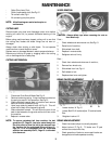
- Cutter Drive Lever Pivot;
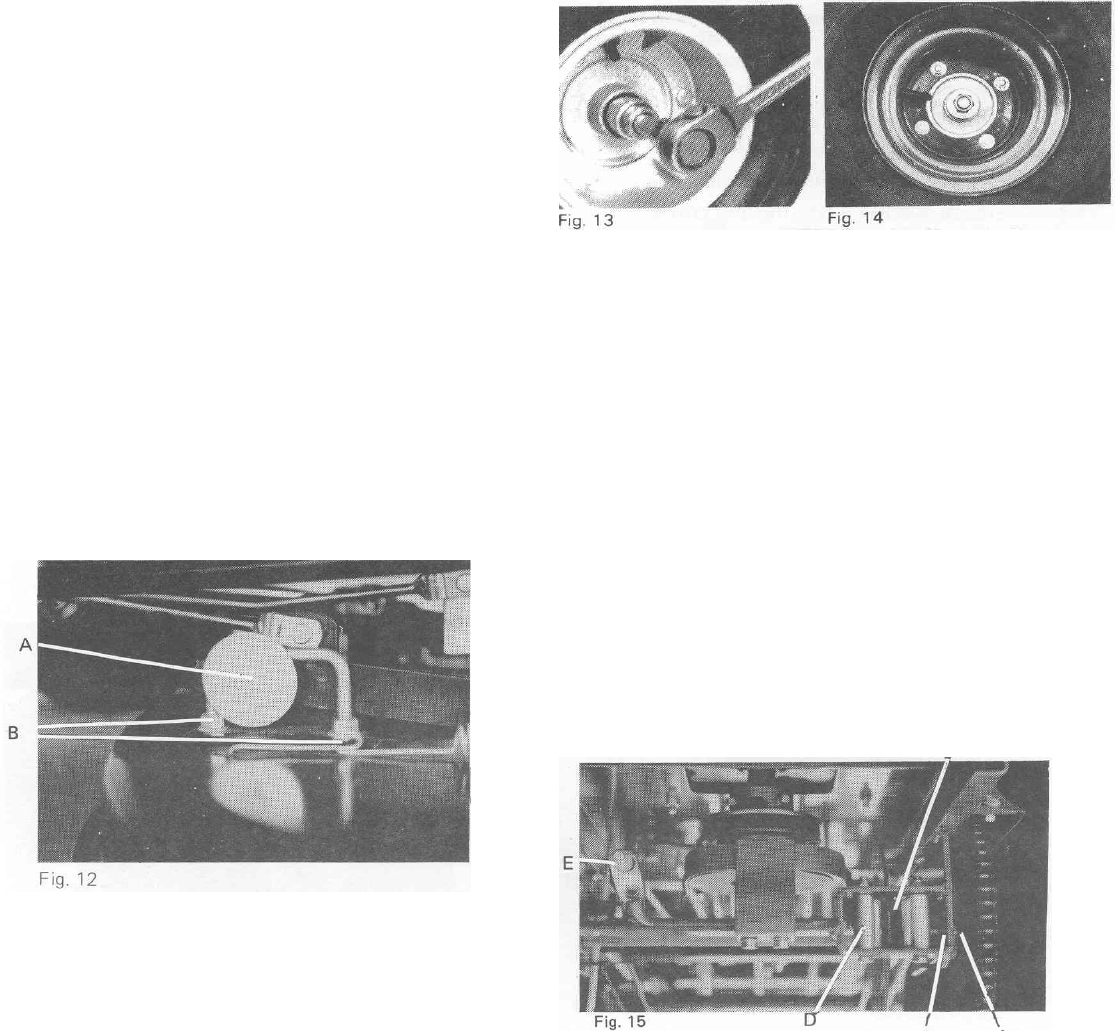
- Clutch/brake pedal pivot; See Fig.15
- Tie rod ball ends; Fig.11
- All connecting rod pivot points.
NOTE: All ball bearings are sealed and require no
maintenance.
CUTTING UNIT:
Remove spark plug lead and disengage cutter drive before
working on cutter unit, to prevent accidental starting of the
engine.
Before using machine always inspect cutting unit to see that
the cutting disc, blades and blade fixings are not worn or
damaged.
Always check after striking a solid object. Do not operate
machine when unusual vibration occurs.
Replace worn or damaged blades in sets to preserve balance.
Remove any build-up of grass or clogging within the cutting
unit or discharge chute or safety flap.
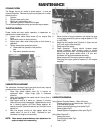
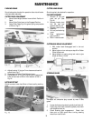
CUTTING UNIT REMOVAL
1. Disconnect Push Rods & Brake Rod Fig.12
2. Remove tensioning spring. A loop has been provided on
the spring to assist in this operation; See Fig.12
3. Slide cutterdeck towards back of machine and remove
belt from around cutterdeck pulley.
4. Undo large retaining washer bolts (A) Fig.12. This will
allow front of deck to be lowered to ground.
5. Slide cutterdeck forward. This will allow the rear of the
deck to be lowered to the ground and be slid from under
the machine.
6. Replace in reverse order.
NOTE: To remove cutterdeck belt from machine, the belt
guard Item 52, Page 20, has to be moved away from
the drive pulley to allow the belt to be removed from
the V-groove and the cutterhead lifting rod Item 15,
Page 16, is to be disengaged from the cutterhead
selection arm assembly Item 5, Page 16 to allow belt
to be drawn out.
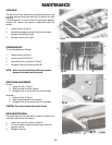
WHEEL REMOVAL
CAUTION: Always deflate tyre before removing rim nuts on
front wheel only.
Front –
1. Chock wheels and remove axle nut; See Fig.13
2. Raise front of machine;
3. Slide wheel from shaft;
4. Replace in reverse order;
5. Retighten axle nut firmly.
Rear –
1. Chock front wheels and raise rear of machine;
2. Remove four wheel nuts;
3. Slide wheel from hub; Fig.14
4. Refit wheel to hub
5. Replace wheel nuts and tighten.
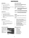
BRAKE CALIPER ADJUSTMENT C
B A
1. Loosen locknut ‘A’ Fig.15
2. Loosen Bolt ‘B’ till brake caliper ‘C’ touches brake
Disc.
3. Retighten Locknut ’A’
BRAKE ARM ADJUSTMENT
1. Check that brake caliper is correctly adjusted;
2. Adjust locknut ‘E’ Fig.15. Till brake arm ‘D’ pad
comes into contact with disc;
3. Check operation of brake to ensure park brake can
be applied, and brake operates correctly.
8