CONTENTS
Section Title Page
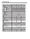
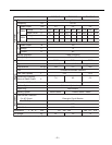
1. SPECIFICATIONS . . . . . . . . . . . . . . . . . . . . . . . . . . . . . . . . . . . . . . . . . . . . . . . . . . . . . 1
2. GENERAL DESCRIPTION . . . . . . . . . . . . . . . . . . . . . . . . . . . . . . . . . . . . . . . . . . . . . . 3
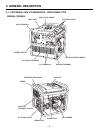
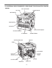
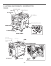
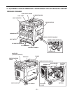
2-1 EXTERNAL VIEW . . . . . . . . . . . . . . . . . . . . . . . . . . . . . . . . . . . . . . . . . . . . . . . . . . 3
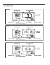
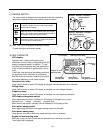
2-2 CONTROL PANEL . . . . . . . . . . . . . . . . . . . . . . . . . . . . . . . . . . . . . . . . . . . . . . . . . 7
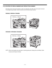
2-3 LOCATION OF SERIAL NUMBER AND PRODUCTION NUMBER . . . . . . . . . . . . 9
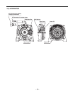
2-4 ALTERNATOR . . . . . . . . . . . . . . . . . . . . . . . . . . . . . . . . . . . . . . . . . . . . . . . . . . . . .10
3. RANGE OF APPLICATIONS . . . . . . . . . . . . . . . . . . . . . . . . . . . . . . . . . . . . . . . . . . . . .11
4. MEASURING AND CHECKING PROCEDURES . . . . . . . . . . . . . . . . . . . . . . . . . . . . .14
4-1 MEASURING INSTRUMENTS . . . . . . . . . . . . . . . . . . . . . . . . . . . . . . . . . . . . . . . .14
4-2 AC OUTPUT MEASURING . . . . . . . . . . . . . . . . . . . . . . . . . . . . . . . . . . . . . . . . . . .17
4-3 DC OUTPUT MEASURING . . . . . . . . . . . . . . . . . . . . . . . . . . . . . . . . . . . . . . . . . . .17
4-4 MEASURING INSULATION RESISTANCE . . . . . . . . . . . . . . . . . . . . . . . . . . . . . . .18
4-5 CHECKING FUNCTIONAL MEMBERS . . . . . . . . . . . . . . . . . . . . . . . . . . . . . . . . .19
5. DISASSEMBLY AND ASSEMBLY . . . . . . . . . . . . . . . . . . . . . . . . . . . . . . . . . . . . . . . . .22
5-1 PREPARATION AND PRECAUTIONS . . . . . . . . . . . . . . . . . . . . . . . . . . . . . . . . . .22
5-2 SPECIAL TOOLS . . . . . . . . . . . . . . . . . . . . . . . . . . . . . . . . . . . . . . . . . . . . . . . . . .22
5-3 DISASSEMBLY PROCEDURES . . . . . . . . . . . . . . . . . . . . . . . . . . . . . . . . . . . . . . .23
5-4 REASSEMBLY PROCEDURES . . . . . . . . . . . . . . . . . . . . . . . . . . . . . . . . . . . . . . .38
5-5 RECOIL STARTER . . . . . . . . . . . . . . . . . . . . . . . . . . . . . . . . . . . . . . . . . . . . . . . . .49
6. TROUBLE SHOOTING . . . . . . . . . . . . . . . . . . . . . . . . . . . . . . . . . . . . . . . . . . . . . . . . .54
7. WIRING DIAGRAM . . . . . . . . . . . . . . . . . . . . . . . . . . . . . . . . . . . . . . . . . . . . . . . . . . . .57
This manual covers only alternator and control unit portion of the generator.
As to the servicing information of engine portion, please refer to the “EX13, E17, EX21 and EX27” service manual.
The specifications and information included in this manual were in effect at the time of printing.
FUJI HEAVY INDUSTRIES LTD. reserve the right to change the specifications and to make modifications in the
course of technical progress, at anytime without notice.
No parts of this manual may be reproduced without written permission.


