


– 20 –
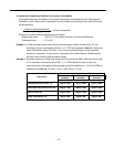
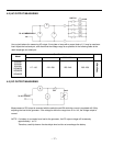
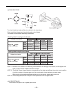
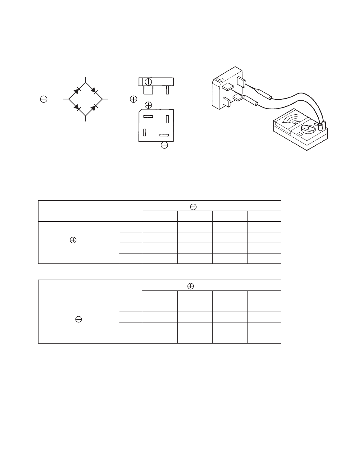
(3) DIODE RECTIFIER
The circuit inside the diode rectifiers is as shown in the chart above.
Check continuity between each terminal by using a circuit tester.
The rectifier is normal when continuity is as follows:
Diode rectifier
Circuit tester
Yellow
Yellow
Yellow
Yellow
Gray
Gray
Orange
Orange
Yellow Yellow Orange Gray
Apply black needle of the circuit tester
Continuity
-
Yellow
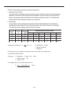
Checking table for analogue circuit tester
Analogue circuit tester
Continuity
No continuity
Yellow
Apply red needle
of the circuit tester
ContinuityContinuity
Orange
-
No continuity
No continuity
-
Continuity
No continuity
No continuity
No continuity
-
No continuity
Gray
Yellow Yellow Orange Gray
Apply red needle of the circuit tester
Continuity
-
Yellow
Checking table for degital circuit tester
Degital circuit tester
Continuity
No continuity
Yellow
Apply black needle
of the circuit tester
ContinuityContinuity
Orange
-
No continuity
No continuity
-
Continuity
No continuity
No continuity
No continuity
-
No continuity
Gray
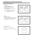
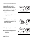
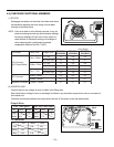
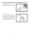
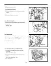
(4) AC RECEPTACLES
Check that no live part or wire or plastic part is burnt.
NOTE 1 : Because of the difference of measuring method between the analogue circuit tester and the digital circuit
tester, polarity of tester needles should be reversed.
NOTE 2 : "Continuity" means forward direction characteristics of the diode, and different from short circuit condition
(in which a pointer of the tester goes out of its normal scale), shows resistance to some extent.
When results of the checking indicates failure even in one section, replace with a new one.
NOTE 3 : Some analogue testers like "Simpson" brand operate as some as digital testers.