


– 19 –
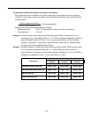
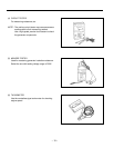
4-5) CHECKING FUNCTIONAL MEMBERS
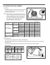
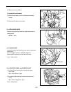
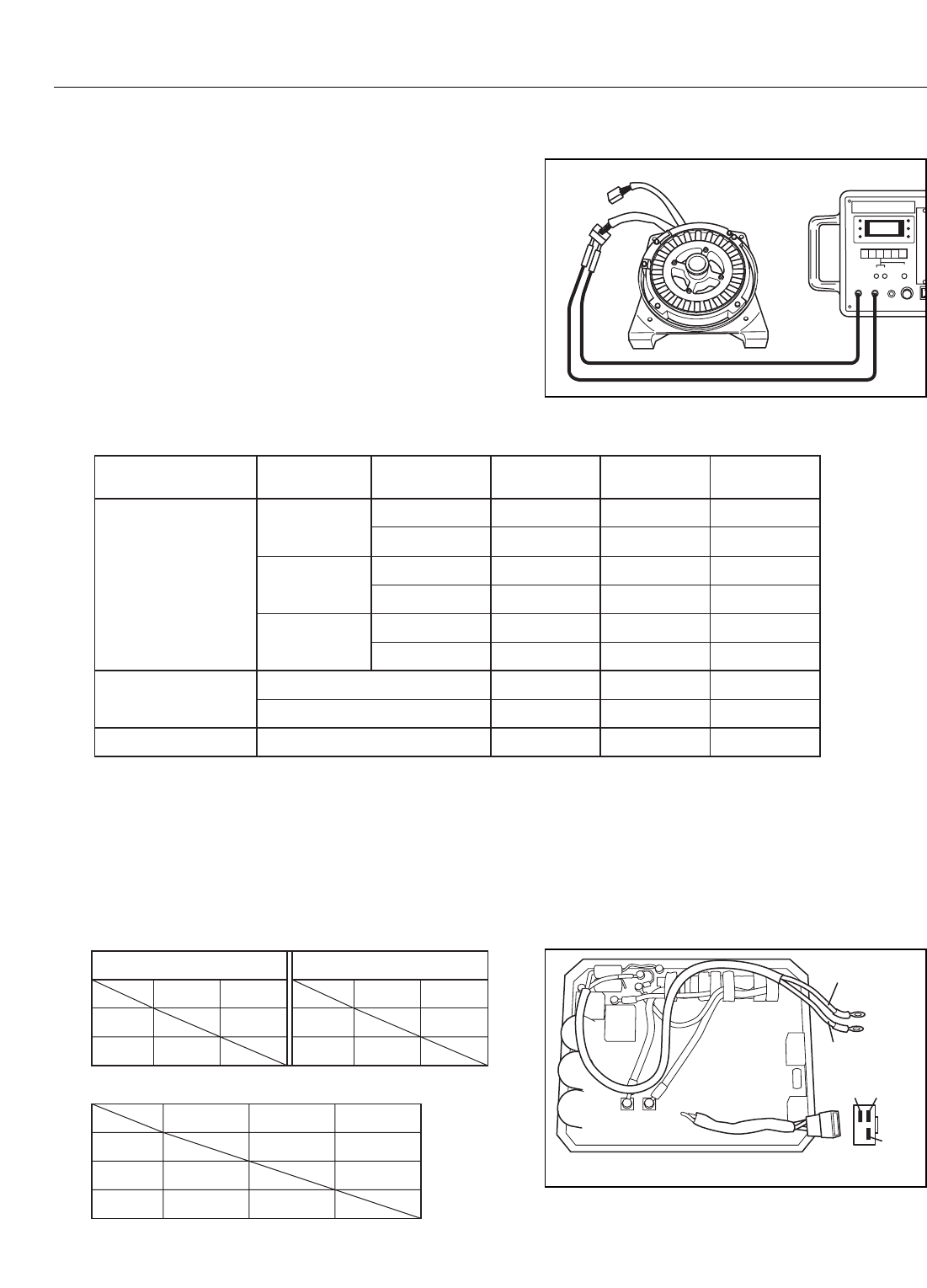
(1) STATOR
Disengage connectors on the wires from stator and check
the resistance between the wires using a circuit tester
referring to the table below.
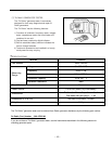
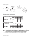
NOTE :
If the circuit tester is not sufficiently accurate, it may not
show the values given and may give erroneous readings.
Erroneous readings will also occur when there is a
wide variation of resistance among coil windings or
when measurement is performed at ambient
temperature different from 20 C (68 F).
RG3200i
RG3200iS
RG2800i
RG2800iS
Connector Wire Color
2.84.0
Red – White
Unit: Ohms ( )
0.81.1
White – Blue
4P Connector
(AC Output Wires)
0.81.1
Blue – Red
Voltage Spec.
220, 230, 240
110, 120
110, 120
0.20.2White – White
8P Connector
0.10.1Brown – Brown
0.10.1Yellow – YellowRectifier Connector
RG4300i
RG4300iS
2.1
0.8
1.1
2.84.0220, 230, 240
2.1
2.84.0220, 230, 240 2.1
110, 120 0.5
0.5
0.5
0.2
0.1
0.1
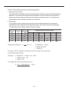
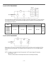
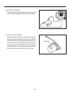
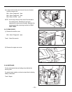
(2) INVERTER UNIT
Check if there is any change of color or blister in the filling resin.
Also check that no change of color or breakage is visible on any electronic component or wire or connector of
the inverter unit.
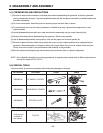
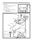
Check the conductivity between the output wires and the 4P connector as per the tables below:
White
Red
Red
BlueWhite
4P Connecter
Red
110V, 120V Specs.
Red
White
White
0.6 k
0.6 k
Output Wires
Red
220V, 230V, 240V Specs.
Red
White
White
2.7 k
2.7 k
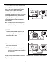
Red
Red
White
Blue
White
5 M
5 M
5 M 5 M
Blue
5 M
5 M
4P Connector