


COMBAT
®
CTCU UNIT HEATERS INSTALLATION OPERATION AND SERVICE MANUAL
42 of 42
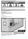
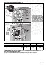
16.7 Ignition Control
This control is mounted at the bracket plate. Pull out
the three cable connectors. Pull out ignition cable,
ignition earth and flame probe cable noting their
positions. Located behind the bracket ignition
control are the white mounting pins. Depress locking
tab while gently pulling bracket away from mounting
pins to disengage the bracket. Remove the screws.
Refit in reverse. Ensure correct location of ignition
and flame probe cables.
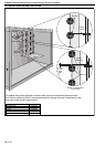
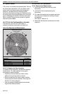
16.8 CTCUA Axial Fan/Guard/Motor Assembly
The axial fan unit for the CTCUA heater is
supplied completely assembled and balanced.
16.8.1 Fan Removal and Replacement
16.8.2 To Replace the Fan Assembly
To replace the fan assembly, reverse the procedure
shown above. Fit rubber washers to the guard
mountings to reduce vibration.
• Check that the fan blades are free to rotate
before turning on the power to the fan.
• Strictly comply with the colour code of the fan
wires to ensure correct operation. See Page 20,
Section 10.3 wiring diagram.
• Use only gen
uine replacement parts sold and
supplied by Roberts-Gordon.
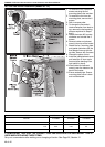
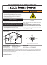
16.9 Fan and Limit Thermostats
16.9.1 Removal and Replacement
1. Pull off the electrical connections to the
thermostat
2. Unscrew the two screws securing the
thermostat
3. Fit a new thermostat with two screws ensuring
that the correct temperature setting and type
are selected.
See Page 9, Section 5.3.
4. Reconnect the electrical connections and test
operation.
Remove the screws
and washers.
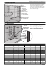
Description Part Number
Axial Fan CTCU-7 11111910
Axial Fan CTCU-11 11111911
Axial Fan CTCU-15 11111920
Axial Fan CTCU-22 11111921
Axial Fan CTCU-27/32 11111922