


COMBAT
®
CTCU UNIT HEATERS INSTALLATION OPERATION AND SERVICE MANUAL
10 of 42
SECTION 6: HEATER INSTALLATION
6.1 General
Heaters are designed for installation above 2.5 m.
These heaters must be installed within the heated
space. Duct delivery systems are not permitted with
axial fans. When handling or supporting the heater
from below, ensure that the weight is taken at the
support points.
6.2 Basic Information
CTCU heaters have automatic ignition burners for
ON/OFF operation only.
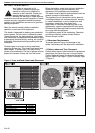
6.3 Location and Suspension
All models:
•Must be installed indoors.
•Must be installed in a level position, with
horizontal or vertical discharge.
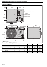
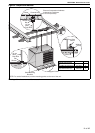
• May be mounted on a shelf of non-combustible
material. (See Page 6, Figure 3 and Page 11,
Figure 4 for support points)
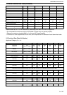
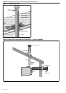
• May be suspended from above (See Page 11,
Figure 4 and Page 12, Figure 5) or from wall
brackets of sufficient strength to support the
heater as listed in the Dimension Data Table on
Page 8, Section 5.1. Drop rods must be a mini-
mum of 10 mm diameter mild steel. Four sus-
pension points (M10 nuts) are located on top of
the heater.
•Must be installed in a manner which allows the
hinged door to be fully opened to provide access
to all serviceable components.
6.4 Handling
All CTCU heaters are su pplied secured to a wooden
pallet and shrink wrapped. Use the pallet to support
the heater during handling and installation. When
handling or supporting the heater from below,
ensure that the weight is taken at the support points.
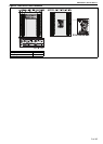
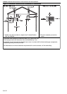
6.5 Suspension and Shelf Mounting
For typical suspension See Page 11, Figure 4.
The gas or electrical supply lines must not be used
to support the heater.
Do not locate the gas or electrical supply lines
directly over the path of the flue products from the
heater.
The heater must be installed in a location that is
readily accessible for servicing.
The heater must be installed in accordance with
clearances to combustibles as indicated on the wall
tag and in this manual.
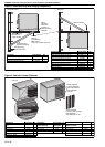
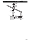
6.6 Wall Mounting
For typical suspension, See Page 11, Figure 4 and
Page 12, Figure 5. Wall mo
unted heaters blowing
parallel to the wall can only be installed with the
service door away from the wall.
The wall mounting brackets must be attached to a
suitable wall using all mounting holes. Screw sizes
less than 3/8" may not be used. In order for the wall
mounting brackets to adequately carry the weight of
the heater, it must be installed according to best
building practices.
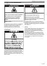
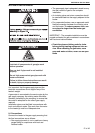
WARNING
Crush Hazard
Use 10 mm steel drop rod minimum.
Failure of the supports can result in death,
injury or property damage.